
SITE INVESTIGATION
INTRODUCTION
• For all civil engineering projects like reservoirs, dams, tunnels, roads,
bridges, and buildings, a detailed knowledge about the project site is
very necessary. It is essential to investigate the engineering properties of
rock or soil at the site.
• Site investigation is defined as the overall evaluation of specific site
condition which is selected for construction of any civil engineering
infrastructure. The geological investigation of the project site is simply
termed as site investigation.
• Main objectives of site investigation are to determine
• the lithology (rock / soil type) of the area,
• the geological structures of the area,
• the groundwater conditions in the region,
• the seismicity (seismic condition) of the region.
PURPOSE OF SITE INVESTIGATION
The purpose of site investigation is to evaluate the impact of
construction on existing site conditions and on proposed
construction, to anticipate what can be excepted during
construction and to develop criteria for design and
construction based upon determined site specific physical
parameters.
Stages of site investigation
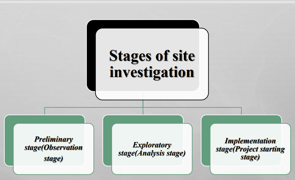
PRELIMINARY STAGE
These stages of study address geologic factors that are important in determining:
• The relative suitability of alternative sites
• The extent of detailed investigation required for construction
• Geologic information for basing reasonable cost estimates
SITE EXPLORATION
• It is the intensive investigation of a site and its results are
incorporated into final design as well as construction of a
project
• Determining and interpreting surface and subsurface
conditions that influence design and construction.
• Evaluation the behavior characteristics and engineering
significance of earth materials present or those intended for
use in construction.
IMPLEMENTATION STAGE
Stage after construction begins
There are two good reasons for following this:
• Geologic conditions encountered during construction may differ
from what was expected and called “changed condition”
• It serves the basis for changing the project design to avoid major
problems in project performance.
TYPES OF SITE INVESTIGATION
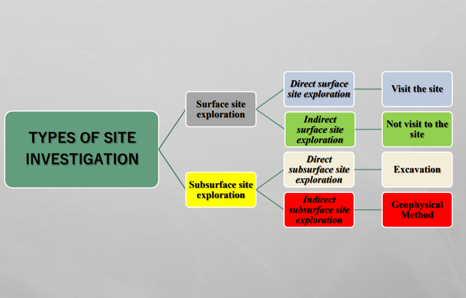
SURFACE SITE EXPLORATION
Direct Surface Investigation
• It is investigation carried out by visiting the actual site
• Information is collected and documented by observation, measurement and
interpretation.
Following major data are to be collected in direct surface investigation
• Type of rock or soil and major component.
• Attitude of rock
• Thickness of soil and rock
• Weathering grade of rock
• Numbers, conditions, nature, weathering, water flow conditions and
condition of discontinuities and their attitude.
• Strength of rock
• Geological structures like bedding, foliation, joints, faults, fold etc.
• Slope stability factors, natural slope and landslides
• Presence or absence of major engineering structures like canals, dams,
tunnels, bridge etc.
• Topography, drainage system, catchments area, flood level etc.
Indirect surface investigation
• In this investigation preliminary idea can be obtained about any specific
site by not visiting directly in the site.
• There may be different means by which this investigation can be carried
out;
• Review of previous literatures including geological maps if available.
• Topographical map analysis; slope drainage network, existing
structures.
• Remote sensing : Study and interpretation of aerial photograph and
satellite image using Stereoscope
METHOD OF SITE INVESTIGATION
Topographic Map:
Topographic map is an orthographic projection of three-dimensional
expression of the topography or elevation relative to the mean sea level. The
map basically comprises features to show elevation (contour lines), rivers and
tributaries, land utilization, distribution of infrastructures, and political
boundaries. Map scale, north pointing arrow, and legends used in map are
also included with geographical as well as Cartesian coordinates.
Topographic map gives basic surface morphological information, and also
some clues about the geological structures and type of lithology. Landforms
and drainage patterns in any area can be mapped with the help of topographic
map of that region. Profiles can also be drawn from the topographic maps.
Satellite Imageries:
These images are taken by satellites in a regular time interval from a specified
height. The sensors assigned in the satellite send rays to land surface and
receivers in the sensors receive the reflected rays at the same time.
Interpretation of satellite images are used in site investigation.
Geological Map:
A geological map depicts the distribution of rocks and soils on the surface
from which the subsurface extension of rocks can be inferred. A geological
section along a desired line is drawn on the geological map that shows the
vertical distribution of rocks along the profile line. A geological map shows the
distribution of lithology, geological structures and their orientations in symbol.
The contact between two rock types is parallel to the strike line. Using the dip
direction and dip amount given in the geological map, thickness of strata can
also be calculated. Horizontal thickness of strata is just horizontal
measurement of strata on map, vertical thickness is the elevation difference
between the upper and lower boundaries of strata. Thematic maps that depict the distribution of different rock types with geological
structures and order of superposition
A geological map gives information on:
1. Positional attitude of bedrocks
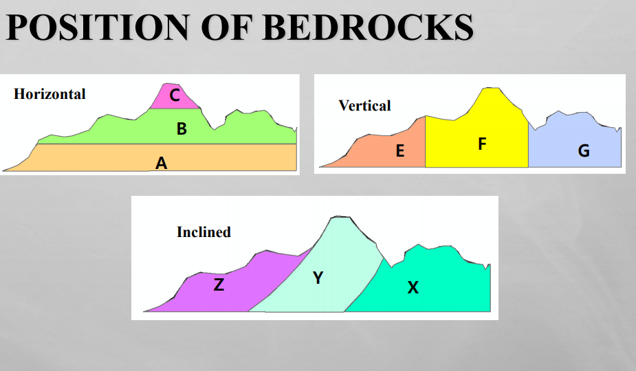
• Horizontal
• Vertical
• Inclined (Dipping with some angle)
2. Geological structures
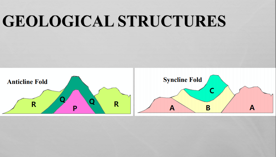
• Folds
• Faults
Engineering Geological Map:
Engineering geological map comprises engineering geomorphic units,
condition of bedrock and soil, distribution of mass movement activities, and
hydrological features. The main purpose of this map is to deliver the
information that is essential to engineering purposes such as construction of
infrastructures. Engineering geological map is also based on the topographic
map of the region and includes information from both geological map and
topographic map. Information from aerial photographs and satellite images
can also be incorporated to make it more reliable. Generally, engineering
geological maps are prepared along road sides and other engineering project
sites.
Gravitational Methods
Earth itself has a gravitational property. Rock and
soil materials also have their own gravitational properties. In the analysis, it
is assumed that the earth is ideally homogeneous in nature. The gravity
value observed in the particular material is compared with the ideal gravity
value. This difference is gravity is called a gravity anomaly. Gravimeter is
used to measure the gravity anomaly and the values are interpreted to
identify the materials such as salt domes, metallic ore bodies, etc.
Magnetic Methods
It is one of the oldest geophysical methods used in
exploration of subsurface earth. Earth is a magnet itself with definite
magnetic field. The magnetic intensity can be measured in any part of the
earth. Since, the earth is not really homogeneous, the observed value of
magnetic intensity differs from the theoretical value. The difference is called
magnetic anomaly. Highly magnetic rock bodies or metallic ore bodies can
be distinguished from less magnetic and non-metallic masses using this
method. This method is generally used in prospecting for magnetic ore
bodies and for oil exploration.
SUBSURFACE INVESTIGATION
Direct Subsurface investigation
• Exploratory excavations: digging pits or
trenches, dozer cuts tunneling
• Borehole exploration : Drilling , Logging
• Depending upon the importance of the project,
budget available and the extent of detail
information needed, the spacing of drilling or
digging may vary
• Hence subsurface exploration may be project
specific and budget specific.
Indirect subsurface Investigation
• Mainly geophysical methods are used for indirect subsurface investigations.
Following geophysical exploration methods can be used for the subsurface
investigation:
• Seismic methods, electrical resistivity methods, gravity and magnetic
methods, electromagnetic methods
• Using the data from geophysical methods and their correct interpretation,
following data can be obtained:
• Type of material, ground water level, contact between geological
formations and their thickness. Presence of aquifers or other structures
like fault, fold and other discontinuities and also economically valuable
materials and buried ancient heritage or engineering structures.
GENERAL PRINCIPLES
• Most common procedure of investigation is drill holes and
sampling.
• Borehole drill machine is called drill rig.
• Investigation depends upon ground conditions, Hard or soft
ground
• Should be economical
DRILLING AND SAMPLING IN SOIL MATERIAL
Bore Holes drill holes
• May be vertical or oblique
• Drilling fluid (mixture of
Bentonite) is used for stabilized
the bore holes.
• Casing is also used for the
protection of walls.
DRILLING METHODS AND EQUIPMENT
• The rotary or core-drill :
Motor is connected to a drill head which actuates a drill rod with a bit at the end.
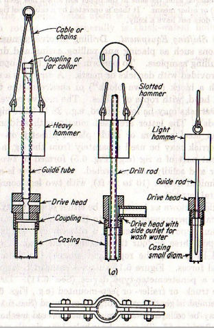
• The cable tool, or churn:
Hammering or percussion action with a help of “string to tools”
• The auger rig:
Advanced by a rotational movement combined with application of pressure. Hand auger rig is used up to 20ft.
WASH BORING
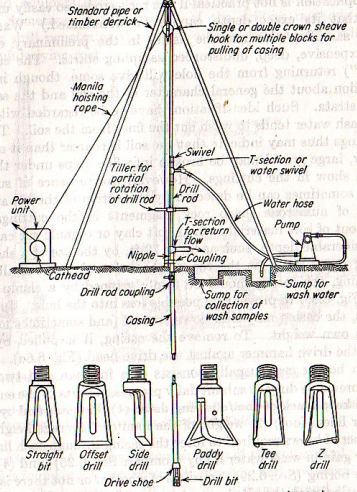
ROTARY AND PERCUSSION DRILLING IN SOIL
• Very successful in rock drilling because of wash
water and high speed of rotation
• It is not generally used in sandy or clayey
materials.
• It is slow method and it is successful in alluvial
and gravel glacial deposits.
Augur Borings
• Advanced by a rotational movement combined with application of pressure. Hand auger rig is used up to 20 ft.
• Hand-held power augers generally can excavate a hole from 4 to 6 in diameter.
• Auger drilling does not require wash water
• Pressure auger is used for more than 20 ft depth up to 100ft.
• Supersaturated sand and boulder and hard strata is the most difficult to penetrate through this method.
DRILLING IN HARD MATERIAL
Core boring: Equipment and methods
• To obtained a samples of a rather hard material
• Cylindrical shape core
• Done by rotational process (40 to 1000 rpm)
• Depth of core boring depend upon the structure and the local geology.
• Water, drilling mud, or air is used in core boring.
• The samplers used generally are termed core barrels.
EXPLORATORY DRIFTS AND TUNNELS
• Drift are tunnel with one entrance
• A drift usually is 4 to 6 ft wide and 4 to 8 ft high
• Drift slope towards the entrance to facilitate drainage and removal
of the excavated materials.
• The main purpose of a drift is to permit detail examination of
joints, fractures, and other rock condition
DRILLING SAFETY PRACTICE
• Drilling dangerous only when the operations become careless.
• Gloves, and careful handling of he equipments are the most
essentials
• Loose cloths should be avoided
• Helmet is necessary
• Should be very careful during the handling of the Heavy objects
• Mask is necessary protect from fuel smoke and dusts during the
drilling time
LOGGING AND LOGS
• Contents of bore hole logs
• Logs of soil materials
• Logs of core boring
• Electrical logging
• Radioactivity logging
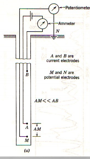
ELECTRICAL LOGGING ON BORE HOLE
• A system of electrodes is lowered into
the hole on a multiconductor cable,
and the reading are recorded.
• The basic propose of this method is to
obtain the in-place resistance to the
flow of electrical current, or the
resistivity of the rock materials at
various depth, and, in addition, the
natural electrical potential developed
in the bore hole.
• Resistivity is measured in ohms meter
squared per meter of the depth
(Ωm2/m) which amounts to ohm times
meter, or ohm-meter.
RADIOACTIVITY LOGGING
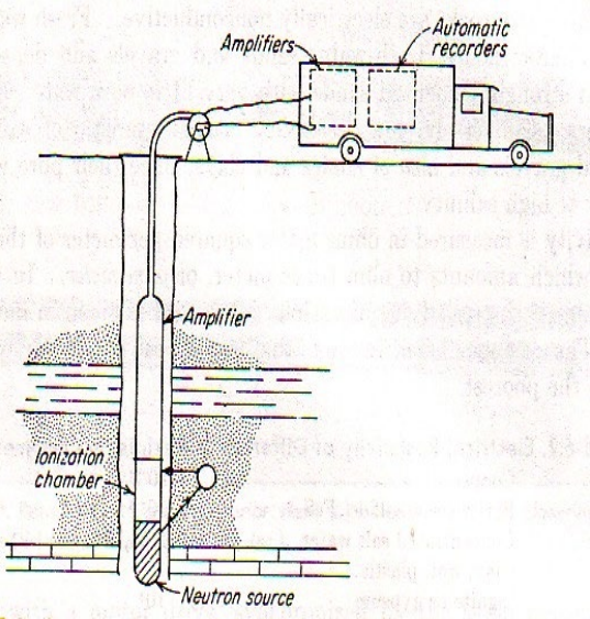
• Radioactivity logging ,First method,
neutron logging, has much in
common with the neutron scattering
method as used for the determination
of the moisture content in soil.
• Source is formed by combining
beryllium Nine (Be9), with helium
four, (He4) ionized chamber filled
with an inert gas.
• Other method is the γ-ray method
where it is considered that all rocks
contain measureable quantities of
radioactive materials which release γ
rays. When y rays stike the gas in the
ionization chamber, it ionize.
GEOPHYSICAL EXPLORATION
• Seismic measurements
• Resistivity Measurements
• Magnetic and Gravity
measurement
• Accuracy of geophysical
methods
SEISMIC MEASUREMENTS
• Seismic Refraction Method is the most common
method, in which involves the creation of a small
shock at the earth’s surface either by the impact of a
heavy instrument or by exploding a small dynamite
charge and measuring the time required for the
resulting sound, or sock, wave of propagation as light
rays and may me reflected or refracted at any
interface where a velocity change occurs.
• The travel time of wave depends upon the media
through which it passing.
• Wave velocities on unsaturated strata 1500 to 3000
ft/sec
RESISTIVITY MEASUREMENTS
The electrical resistivity of a portion of the ground at a site is measured as follows.
• To determine the resistivity of the ground, current I that flows from the batteries and through the ground between the current electrodes is measured on the milliammeter. Voltage V between the potential electrodes is measured on the potentiometer.
ρ =2Πα (V/I)
MAGNETIC AND GRAVITY MEASUREMENT
• In magnetic procedure, a magnetometer is used to measure the vertical component of the earth’s magnetic field at closely spaced stations in an area.
• In the gravity method, a gravimeter is used. Measurements are made of the force of gravity at certain field station and corrected for variations as necessary. The corrected gravity values reflect condition below the surface.
ACCURACY OF GEOPHYSICAL METHODS
The geophysical methods, as are other methods, are applicable only where the
basic assumptions of the method used are valid.
• For seismic survey, Problem arise if underlying rock has some or lower velocity
than that of overlying rock or overburden
• Problem arise when the surface terrain are steep slope, unevenness
• The resistivity method requires a high resistivity contras between the materials
being located.
• Determination cannot have the degree of accuracy provided by core drilling.
• In the practice of the USBR, where drilling was available for checking purposes, it
was found that seismic-predicted depths to bedrock showed and average accuracy
of 90 to 95 % to depths of about 100 ft.
SITE INVESTIGATION OF TUNNEL
Tunnels are underground routes or passages driven through the rocks or soft ground without disturbing the overlying soil rock cover.
Following geological condition is to be investigated for tunneling
• Attitude of rock: Horizontal or slightly dipping rocks with the strike parallel to the axis of the tunnel is favorable. Steeply dipping
formations with the strike perpendicular to the axis of the tunnel are favorable too.
• Strength of rock: High strength of rock is favorable
• Effect of water on rock: whether it dissolves the rock, deteriorate it or produced no effect.
• Numbers of joints : Minimum numbers of joints, high spacing , rough joint plane or stepped, no or little weathering along joints is
favorable
• Geologic structures : absences of any structure like faults, fold, and unconformity
• If folded, anticline is favorable since the vertical pressure relieved and do arch action by the up arch position.
• If faulted, first to consider if it is active, if a tunnel intersects an active fault nothing can be done to protect structure, so alignment
has to be shifted. Even if it is not active , better is looking for other options
• Water table condition: Water table below the tunnel is favorable. If tunnel is located below water table, a sand like suspension may
rush into the tunnel.
• Cost: Project with minimum cost is desirable. If blasting has to be done or not, Tunnel boring machine is needed or excavations are
enough. If yes which part, for what length and what cost. Which part needs support and what type, if water is likely to be encountered in what part and what amount.
SITE INVESTIGATION OF BRIDGE
• Geological structure : like fold\, fault and unconformity should be avoided
• Rock mass strength: should be high (competent bed), less fracture, joints in rock is
favorable.
• Attitude of rock: rock dip opposite to the water is favorable.
• Weathering : less weathered rock is favorable
• Expansive soil to be avoided.
• Lateral erosion (bank scouring) : the intensity of bank scouring in the site should be less
Span of river: Narrow Span of river is desirable
• Drainage and catchments area: should be studied with available data on flood level.
Particular attention needed to the origin, discharge and periods of high water.
• – Environment Impact: the effect of structure to the surrounding region and that
of surrounding region to the structure to be studied.
SITE INVESTIGATION OF RESERVOIR
• Permeability investigation-A reservoir is meant to hold water; hence the rocks and soils around as well as below it should
form an impervious basin without need of excessive and expensive grouting.
• Limestone and to some extent sandstone with calcareous cement may present serious hazard
• Coarse sandstone, gravels, sand and glacial deposits are highly permeable whereas un-jointed igneous rocks and massive
limestone are impermeable
• Geological structure to be avoided. The syncline fold plunging upstream can be favorable but anticline is unfavorable
• Groundwater conditions: high water table conditions are favorable since there will be flow of water from reservoir bank to the
reservoir in low water table case, there is possibility of flow of water from reservoir to the rock.
• Siltation problems
• Sedimentation of the reservoir with passage of time
• Siltation will make the project failure by reducing the storage capacity
• Stream velocities along with the nature of tributaries and rock type through which it flows dictate the siltation problems
• Topography, climate, vegetation are to be studied since they can affect it.
• Check dams, installation of outlets, silt basin and watershed improvements are methods of checking siltation.
SITE INVESTIGATION OF DAM
• It is a solid barrier constructed across a river valley with a view of impounding water. Following
parameters are to be studied during dam site selection
• Technically strong, impermeable and stable site
• Construction material: should not be far from the construction site
• Lithology should not vary at the site, Hard massive igneous rocks are best. Massive sedimentary
rocks with siliceous cementing materials are also good.
• Stress condition: if acted, normal to bedding plane is favorable.
• Attitude of rock: Horizontal beds or beds gently dipping towards upstream are favorable. Strike
parallel to the resultant stress is most unfavorable
• Geologic structures: should be avoided, but small scales fractures and faults can be grouted. In
syncline fold, water leakage from beneath the dam may occur.
• Environment impact: Effect of structure on surrounding and of surrounding to the structure to
be studied.
• Catchments area, flood levels etc. are to be studied and necessary countermeasure for them to be
performed in case necessity.
GEOLOGIC CRITERIA FOR ROAD
In hilly and mountainous terrain with bedrock
• The road alignment should avoid the active geological structures
such as fault, thrust, and axis of folds
• Hard and less discontinuous rocks are more suitable
• Inclination of bedding and discontinuities should favor the slope of
terrain to reduce the slope instability
• Rocks with high strength and less weathering and erosion
characteristics are more suitable
• Rocks with karst and caverns should be avoided as possible
• Presence of old landslides and other mass movements should be
considered
• Active landslides and creep zones should be avoided
In hilly and mountainous terrain with soil
•If the soil is colluvium, the slope gradient with more than 25o is
not suitable
• The thick soil cover on sloped terrain is not suitable
because it is prone to erosion and slope failure
• Residual soil is indicator of high weathering, so the
characteristic of clay minerals present in that soil should be
considered
• Bearing capacity of soil must be high
• Groundwater, seepage, and springs must be managed
In plain area with soil
• Well-graded soil is more suitable (containing equal proportion of all sizes of soil)
• Naturally compacted soil with high load bearing capacity is suitable
• Silt and sand area with high ground water level are prone to liquefaction. These sites should be avoided as possible
• The surface drain must be well and the road must be raised to avoid inundation
• The site with majority of coarse-grained soil is not more suitable
• The road should not be barrier for surface water
GEOLOGIC CRITERIA FOR FOUNDATIONS/ BUILDING
• Soil and rock characteristics
• Depth of foundation depends on the height and scale of infrastructure to be founded
• Coarse soil is preferable than Fine Grained soil
• Hard and less jointed rock more suitable
• Silt and clay soils with high groundwater table is not appropriate for foundation of large infrastructures
• Soil with high Load bearing capacity is preferable
• High strength and low plasticity soil is good for foundations
• Groundwater condition
• Topographical criteria
• Geological structure
• Natural hazard criteria
GEOLOGIC CRITERIA FOR WASTE DISPOSAL SITE
Topographic features / terrain morphology
• Depression or isolated basin should be preferred
• Highland or steep sloped (> 20o) terrain is not suitable
Rainfall pattern in the locality
• Low rainfall zone is preferred as possible
Nature of surface water flow on the site
• Surface water should not flow through the selected site
Distance from residents and waster sources
• Disposal site must be far from residential area (~1 km)
• Distance from water sources must be more than 500 m
GEOLOGIC CRITERIA FOR WASTE DISPOSAL SITE
Rock /Soil characteristics at site
• Intact rock with less discontinuities and fractures are preferred
• Good aquifer rocks with karst structures should be avoided
• Rock above and below the site should be stable in terms of slope
• Impermeable soil, such as clay is good
• Gravel, sand, and coarse grained alluviums should be avoided
• Site with high groundwater level are not suitable
• Liquefaction potential sites should be avoided
• Seismically inactive sites should be chosen
Reference 1: Text book of Engineering Geology , N Chenna Kesavulu