

Rock Mass Classification
Rock mass: The large volume of rock intersected by discontinuities is known as rock
mass.
The rock mass is heterogeneous in nature due to variation in rock type,
discontinuities and degree of weathering.
Rock mass = Intact rock + Discontinuities
The discontinuities highly influence the overall strength of rock mass.
Strength of rock mass < Intact rock
Intact rock:
The intact rock is the rock in which there is absence of discontinuities.
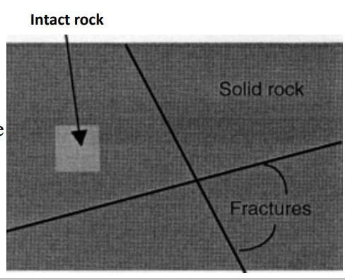
Discontinuities:
Discontinuities are the structural features of rock which are developed due to existence of different stress on the periphery of the earth. Discontinuities includes bedding plane, joints or fracture etc.
Properties of Discontinuities
The properties of discontinuities are:
a) Orientation
b) Spacing
c) Continuity (persistence)
d) Aperture (width) and Infilling
materials
e) Surface Characteristic
(Roughness)
f) Groundwater condition
Rock mass classification system
Different rock mass classification system has been established till now by different researcher. The
rock mass classification helps to improve the quality of site investigation by providing quantitative
information for design purpose. It is also used to determine the strength of rock and help to
determine the support condition required for rock to provide designed strength and leads to
successful completion of project.
Different rock mass classification systems are as follows:
a) Terzaghi’s rock mass classification system
b) Rock quality designation index (RQD)
c) Rock mass rating system (RMR)/ Bieniawski’s/ Geomechanical classification System
d) Rock tunneling quality index ( Q- value)
a) Terzaghi’s rock mass classification
This is the first organized rock mass classification system proposed by
Dr. Karl Terzaghi (1946). The system was mainly qualitative and used
for rock tunnel design and construction projects.
• Intact rock: Rock with no joints and hair cracks.
• Stratified rock: Rock with little strength along bedding surface.
• Moderately jointed rock: Rock mass jointed but cemented.
• Blocky and seamy rock: Jointed rock mass without any cementing of
joints.
• Crushing rock: Rock that has been reduced to sand size particles
without any chemical weathering.
• Squeezing rock: Rock containing considerable amount of clay.
• Swelling rock: Rock that squeezes primarily from mineral swelling.
b) Rock Quality Designation Index
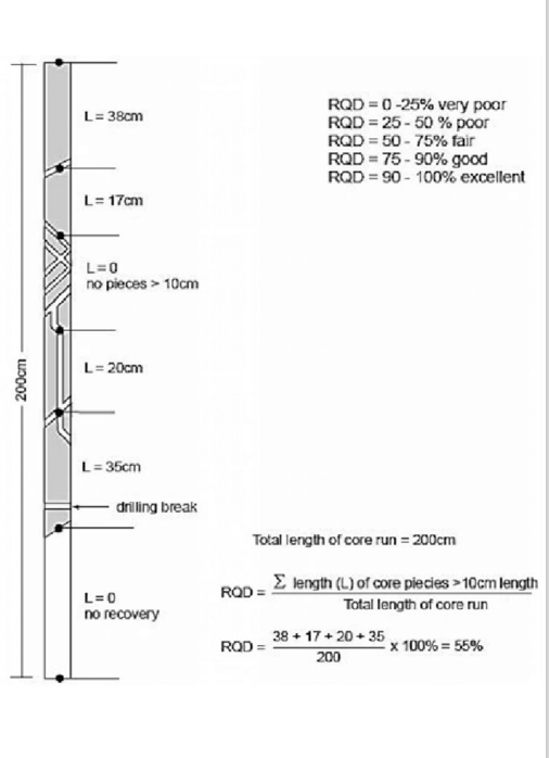
The Rock Quality Designation index (RQD)
was developed by Deere (Deere et al 1967) to
provide a quantitative estimate of rock mass
quality from drill core logs. RQD is defined as
the percentage of intact core pieces longer than
100 mm (4 inches) in the total length of core.
Sometime the drilling core is not available in such case the RQD can
be determined by the relation suggested by Plamstrom as shows
below:
RQD = 115 – 3.3 Jv
Where,
Jv = Sum of no. of joints per unit length of all discontinuity sets
known as the volumetric joints count.
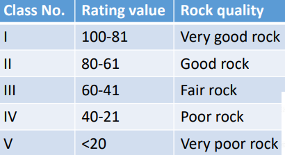
Rock are classified into various groups based on RQD:
c) Rock mass rating system (RMR)/ Bieniawski’s/ Geomechanical classification System
Bieniawski (1976) published the details of a rock mass classification
called the Geomechanics Classification or the Rock Mass Rating (RMR)
system. He has given different rating to different parameter. The sum of
the rating of individual parameter gives the final rating value. The RQD is
used to classify a rock mass using RMR system are:
a) Uniaxial compressive strength of rock material
b) Rock quality designation RQD
c) Spacing of discontinuities
d) Condition of discontinuities
e) Ground water conditions
f) Orientation of discontinuities
Each of the six parameters is assigned a value corresponding to the characteristic of the rock. These values are desired from field surveys and laboratory tests as given in table below:
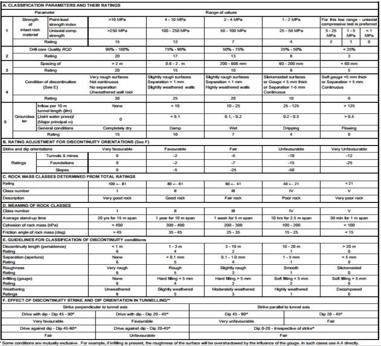
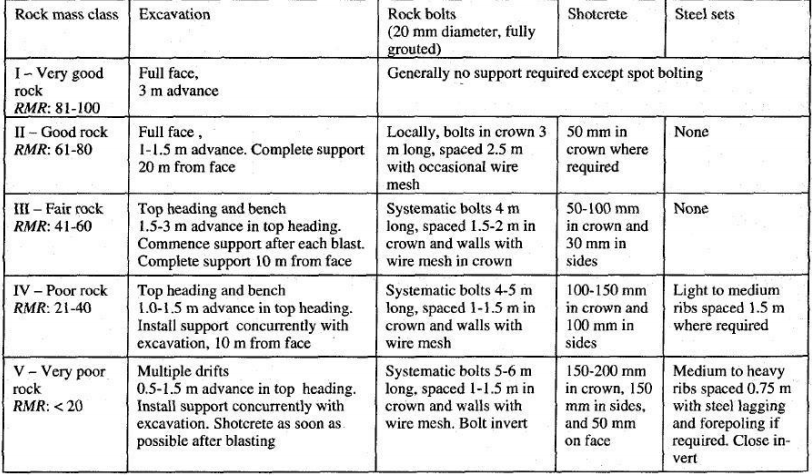
Classification based on RMR
Guidelines for excavation and support of 10 m span rock tunnels in accordance with the RMR system (After Bieniawski 1989).
d) Rock Tunneling Quality Index (Q- Value)
On the basis of an evaluation of a large number of case histories of underground
excavations, Barton et al (1974) of the Norwegian Geotechnical Institute proposed a
Tunnelling Quality Index (Q) for the determination of rock mass characteristics and
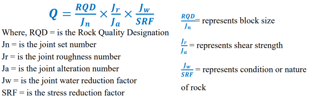
tunnel support requirements. The numerical value of the index Q varies on a
logarithmic scale from 0.001 to a maximum of 1,000 and is defined by:
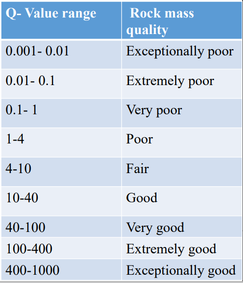
Based on Q-value, rock mass is classified in various group as follows:
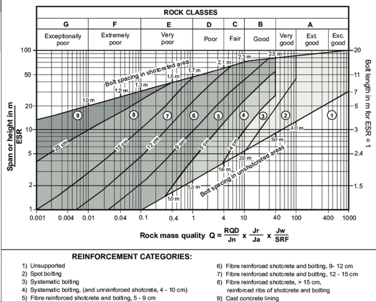
Permanent support recommendations based on Q-values and span/ESR
Slope Stability Analysis:
• Slope stability refers to the condition of inclined soil or rock slopes to withstand or undergo movement. The stability condition of slopes is a subject of study and research in soil mechanics, geotechnical engineering and engineering geology.
• Slope stability analyses include static and dynamic, analytical or empirical methods to evaluate the stability of earth and rock-fill dams, embankments, excavated slopes, and natural slopes in soil and rock. The analyses are generally aimed at understanding the causes of an occurred slope failure, or the factors that can potentially trigger a slope movement, resulting in a landslide, as well as at preventing the initiation of such movement, slowing it down or arresting it through mitigation countermeasures.
Types of slope failure:
a) Plane failure
b) Wedge failure
c) Toppling failure
# Plane failure:
Now take discontinuity whose dip direction is in same direction to hill slope for plane failure analysis. Condition for plane failure:
• Dip direction of hill slope/ cut slope and direction of discontinuity planes must be in same direction.
• Dip amount of cut/hill slope must be greater than that of dip amount of discontinuity.
• Dip amount of discontinuity plane must be greater than frictional angle.
• Additional conditional strike difference must be written 20⁰.
# Wedge failure:
Analysis of the intersection of discontinuity for wedge failure.
Condition for wedge failure:
• Dip direction of hill slope/ cut slope and intersection of discontinuity planes must be in same direction.
• Dip amount of cut /hill slope must be greater than that of dip amount of intersection of discontinuities.
• Dip amount of discontinuity plane must be greater than frictional angle.
# Toppling failure:
Now take discontinuity whose dip direction is in opposite to the hill slope for toppling failure.
Condition for Toppling failure:
• Dip direction of hill slope/ cut slope and direction of discontinuity planes must be in opposite direction
• Dip amount of hill slope should at least 55⁰.
• Dip amount of discontinuity should steeper than hill slope. (dip of h/s < dip of discontinuity)
• Strike difference must within 180±30⁰ (150-180)
Reference 1: Text book of Engineering Geology , N Chenna Kesavulu