
1.1 General layout of components in a typical power plant
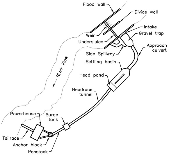
1.Diversion weir:
- Structure built in a river to divert water from the main channel into a canal or penstock.
2.Intake:
- Opening to draw design flow from the river.
3.Gravel trap:
- Used to reduce the velocity of water and prevent erosion.
4.Settling basin:
- Used to capture sediment and other debris.
5.Headrace canal:
- Used to transport water from source to power plant.
6.Penstock:
- Pipe or conduit used to convey water from reservoir to turbine.
7.Power house:
- Building with equipment used to generate electricity from hydropower.
8.Tailrace:
- Outlet channel where used water is released.
1.2 Different type of intake
Intake
Function:
- Control flow of water.
- Prevent entry of debris, trash and ice etc.
- Minimize sediment entry.
Location of intake:
- Should be located at upstream side of power house.
- Located in an area with large and consistent river flow.
- Should be located such it has minimum environmental impact.
- Should be located in area free from debris and sediment.
Types of intake:
1. Runoff river intake:
a.Side intake:
- Common type of intake in ROR plant.
- Suitable for mild slope river.
- Longitudinal axis of the intake is aligned perpendicular to the axis of the river.
b.Frontal intake:
- Suitable for clean and wide river.
- Longitudinal axis of the intake is aligned parallel to the axis of river.
- Trash and debris are attracted towards intake.
c.Drop intake or Bottom rock intake:
- Trash rack is provide over the intake.
- Suitable for very steep river carrying boulder.
- Simple and inexpensive.
2.Reservoir intake:
a.Dam intake:
- It is provided in the body of the dam and used in high head hydroelectric plant.
b.Tower intake:
- Used in large projects.
- Tower intake are categorized as dry tower intake and wet tower intake.
c.Submerged intake:
- Used in small power plants.
- Used in reservoir or river which do not have higher sediment concentration.
- Economical.
d. Shaft intake:
- Vertical shaft driven into the river bed which carries water through underground conveyance system to the power house for power generation.
Importance of intake:
- Helps to ensure a steady flow of water to the turbine. Hence, increasing their efficiency.
- Help to reduce entry of debris in turbine and preventing from damage.
- Used to divert water from one area to another in order to meet demand or balance out river flow.
- Necessary for proper functioning hydropower system.
- Controls water level.
Consideration for location of intake:
- Adequate inflow.
- Least debris intake.
- Least environmental impact.
Design concept in intake:
- Design suitable type of intake based on site and hydraulic condition.
- Satisfy the velocity condition.
- Approach velocity= 1m/s
- Trash rack= 0.6-0.75 m/s
- Intake gate= 1-2 m/s
- Decide number of opening of intake.
- Account for contraction effect due to abutment or piers.
- Calculate hydraulic losses i.e transition loss, exit loss etc.
- Ensure no entry of air.
i.e The system can trap air due to the formation of vertex due to hydraulic jump condition.
- Ensure the release of trapped air to avoid formation of vacuum.
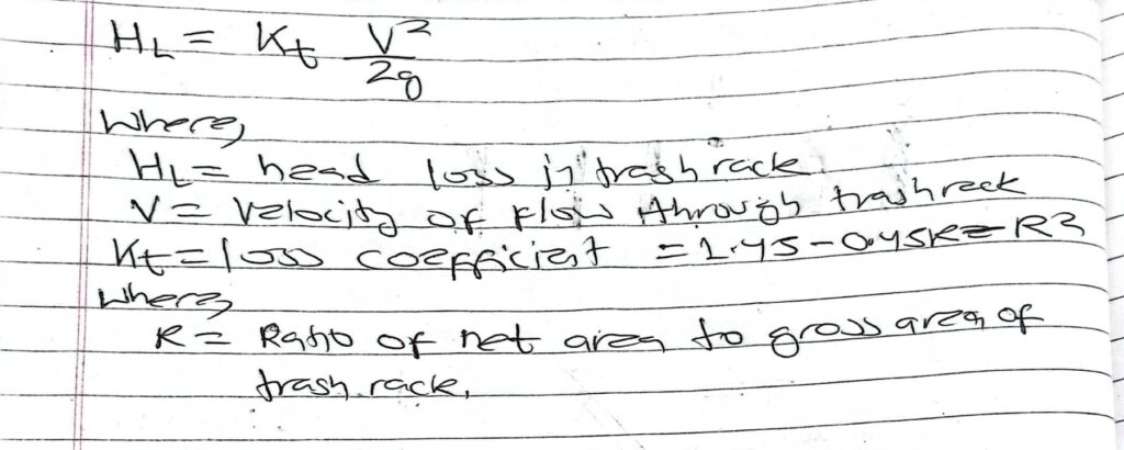
Head loss in trash rack:
a.Kirschmer’s formula
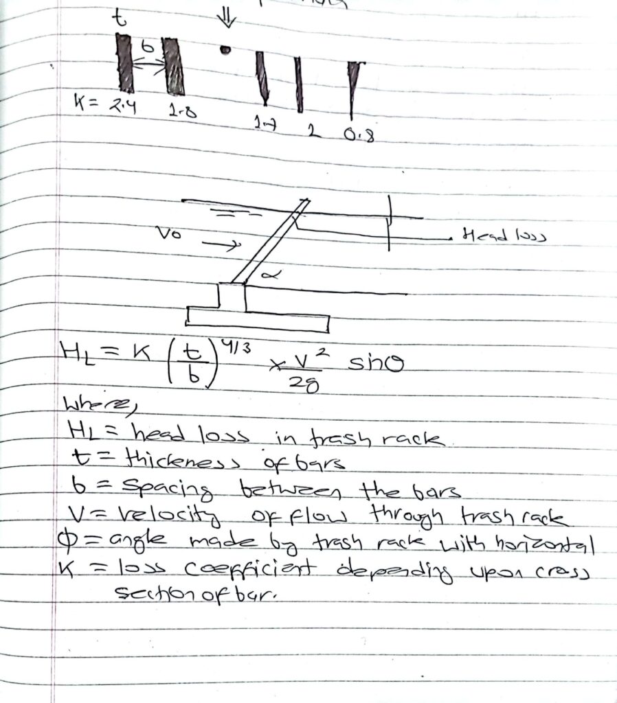
b. General formula
1.3 Performance standards of headwork’s
Control of bed load and floating debris intake
1.Trash rack:
- Placed at the entrance to the intake to prevent entry of floating debris and large stone.
- Trash rack are fabricated with stainless steel or plastic bars.
2.Undersluice:
- Provided to flush out the sediments deposited in front of the intake and control the bed level in its approach area.
- Located close to intake.
3.Gravel trap:
- Constructed close to intake in order to prevent gravel from getting into the canal.
- Main function is to collect the bed load.
- Location is based on the site condition, availability of flushing head and gravel carrying capacity of the canal.
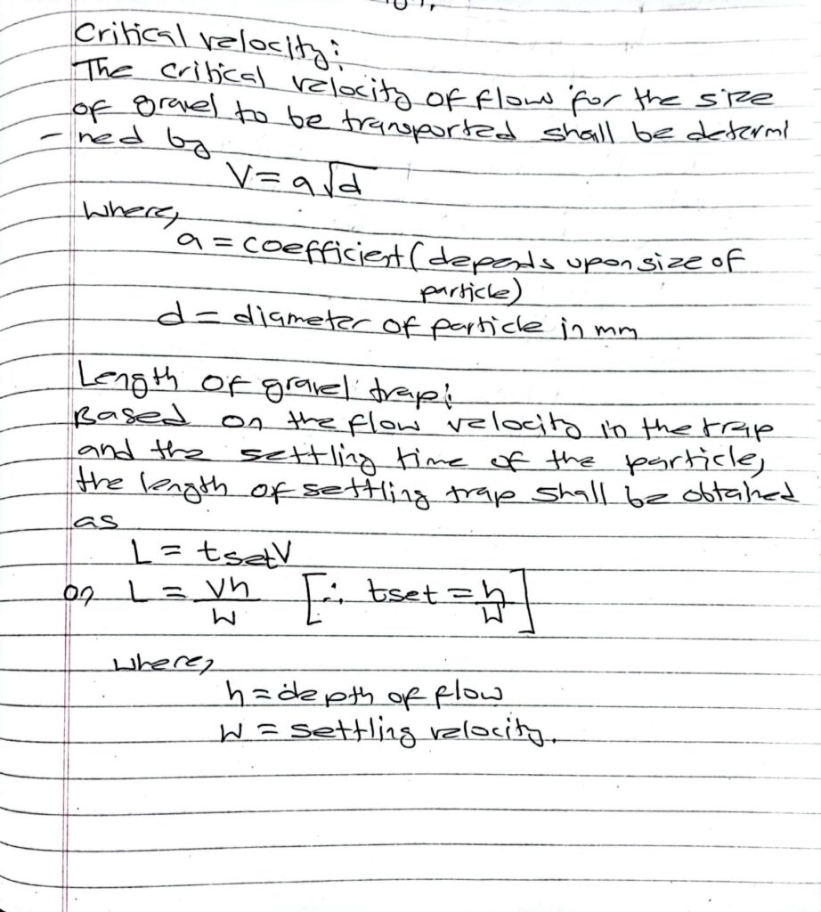
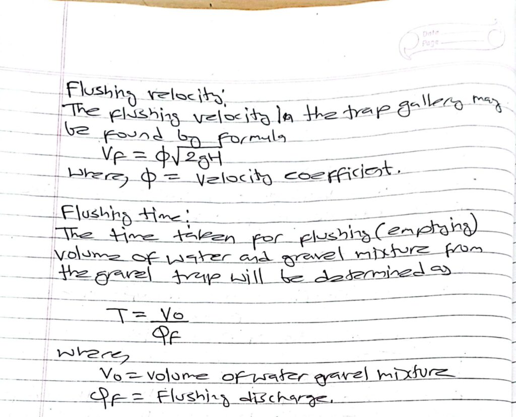
Hydraulic design of gravel trap:
Hydraulic design of gravel trap is similar to settling basin design.
Himalayan intake:
- Himalayan intake is a special type of intake that has proper system for management of both floating debris and bed load.
- It is a geometric design of an intake structure to be used in run-off-river hydropower intake in steep Himalayan river.
- The purpose is to maintain a reservoir volume for daily peaking by providing means of flushing of sediments from reservoir.
- The intake is designed to function in a river which carry both floating debris and large amount of coarse sediments.
1.4 Sediment handling measures
Himalayan river are more prone to erosion due to :
- Young geology
- Fragile geology
- Intense rainfall
- Steep catchment
Sediment handling measure:
1.Catchment management:
- Vegetation screen may be developed by promoting the growth of vegetation in the catchment as well as the entrance to the headwork.
- It would trap a large amount of sediment if flood water pass through them before entering the head works hence helping in reducing the sediment and prevent from entering.
2.Control sediment deposition
- Water having higher sediment content is discharged to the downstream through the undersluice.
3.Construction of sediment excluder or sediment ejector:
- Sediment excluder are constructed in the river pocket.
- Sediment ejector are constructed in the canal.
4.Construction of sloping intake
5.Construction of gravel trap
6.Construction of sedimentation tank
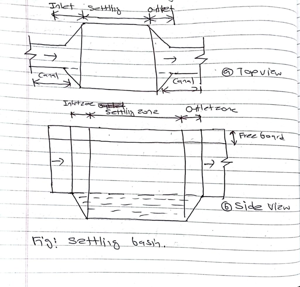
Settling basin:
- It is the structure to remove suspended sediments from the conveyance water for power plant.
- The main principle of the design of settling basin is to reduce the main velocity of the flow.
Purpose of settling basin:
- To remove the fine grained suspended matter from water drawn from intake.
- To remove the suspended particle and minimize the wear and tear of nozzle and runner of turbine.
- To remove sediment as it causes abrasion and erosion of civil structure’s.
- To operate and maintain power plant.
Design criteria of settling basin:
1. Optimum removal of sediment:
- Settling basin shall be designed to remove as much of sediment load in water in econological way.
- As removal of all suspended sediment is not physically possible so the design shall attempt to remove as much of possible so that hydraulic transport capacity of water conveyance sytem is maintained.
2.Settling capacity:
- The size of basin must be large enough to allow a percentage of fine sediment to fall out of suspension and deposited on the bottom.
3.Storage capacity:
- The basin should be able to store the settled particle for sometime unless it is flushed out.
4.Flushing capacity:
- The basin should be able to flush all settled particle along with the incoming flow in the basin by opening flushing gate or valves.
Components of settling basin:
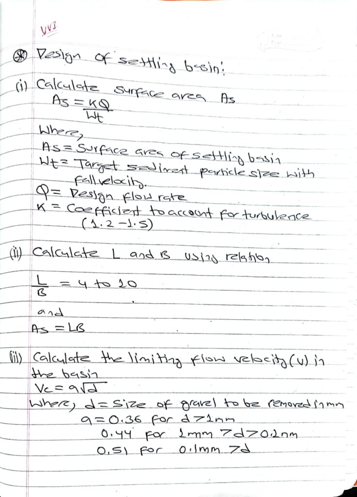
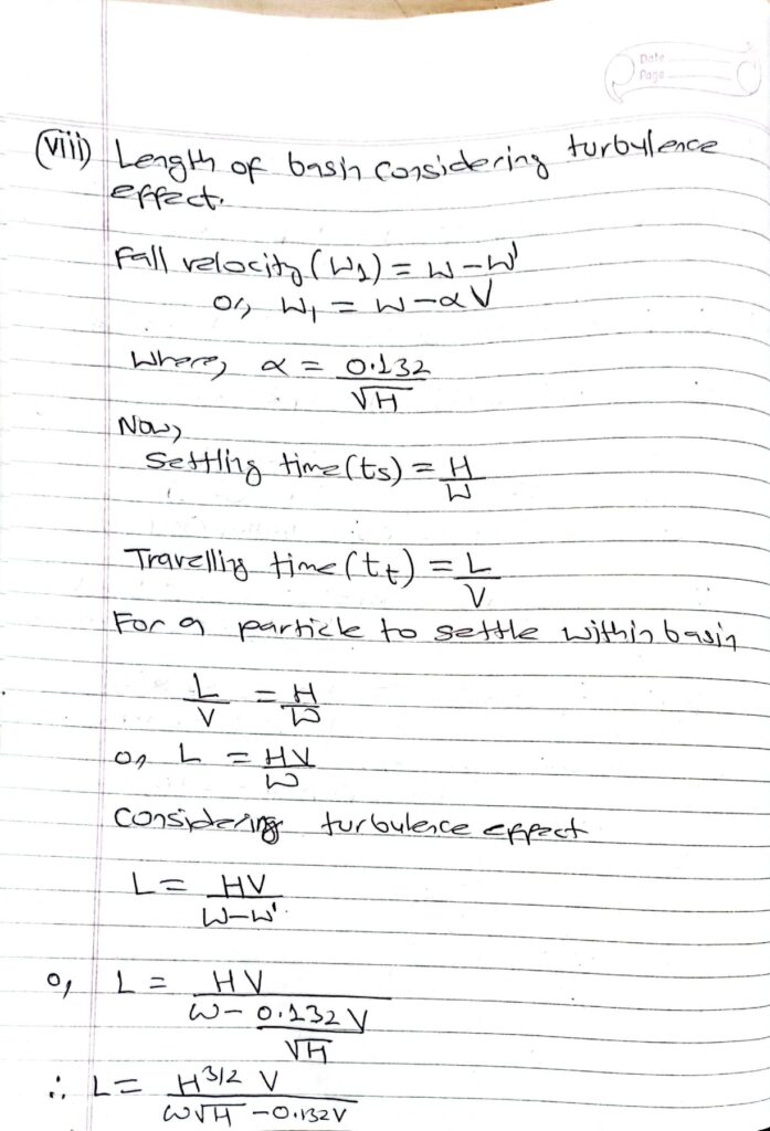
Design of settling basin:
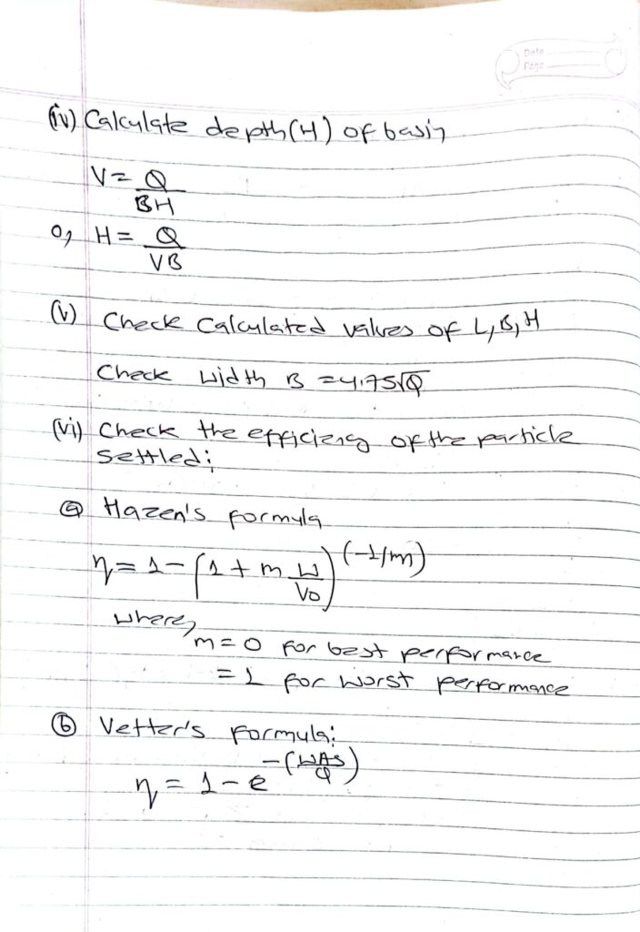
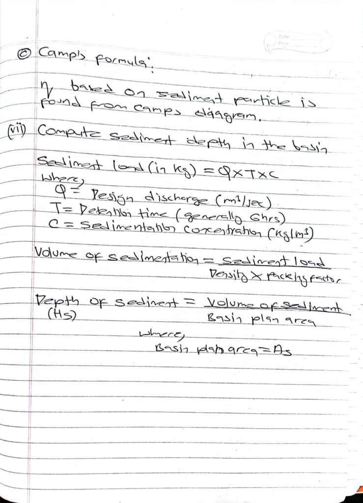
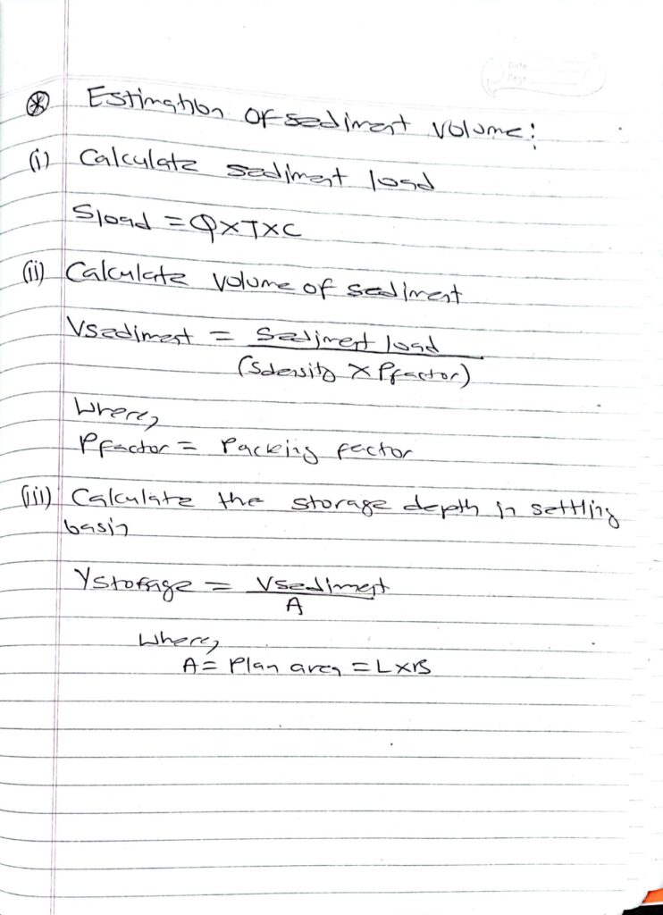
Estimation of sediment volume:
1.5 Flushing of settling basin
1.Continuous flushing type:
- These type of basin are designed with hoppers. The settled particle pass through the bottom of the hoppers to the collecting channel and are flushed continuously.
- Uses surplus water for flushing i.e about 10% of plant discharge.
- Does not interfere in power production during flushing process.
- Complex compared to discontinuous type.
- Main problem is clogging of sediment extracting system.
- Example: Hopper type and Hydro cyclone.
2.Discontinuous flushing type (Periodic or Intermittent):
- Sediment are not flushed continuously.
- Simple in design and are much less susceptible to clogging.
- In first phase, the suspended sediment are allowed to settle in the settling zone.
- In second phase the deposited sediment are removed by different systems.
- Flushing is only required when settling basin is overloaded.
References:
- Dandekar, M. M., & Sharma, K. N. (2010). Water Power Engineering. Vikas Publishing House.
- Punmia, B. C., Pande, B. B. L., Jain, A. K., & Jain, A. K. (2016). Irrigation and Water Power Engineering. Laxmi Publications.
- Singh, Bharat (2018). Fundamentals of Hydrology and Hydropower Engineering. Nem Chand & Bros.
- Central Water Commission, Government of India (2019). Handbook on Hydroelectric Engineering.
- International Energy Agency (IEA) (2021). Hydropower Status Report. Retrieved from www.iea.org
- Nepal Electricity Authority (NEA) (2022). Annual Report on Hydropower Projects in Nepal. Retrieved from www.nea.org.np
- United States Bureau of Reclamation (2020). Design of Small Dams. U.S. Government Printing Office.