
1.1 Introduction to power canal, its suitability in hydropower project
Power Canal:
- A power canal refers to a canal used for hydraulic power generation, rather than for transport.
- Flow is open channel.
Suitability of canal in hydropower system
- Canal can be a good medium of conveyance where construction of tunnel is expensive.
- Construction of canal is easier than tunnel.
- Hydropower can be merged with other purposes if the conveyance system is canal.
1.2 Hydraulic tunnels
Tunnel:
- Tunnel is an underground passage made without removing the overburden.
- They are constructed fort the conveyance of flow or the transportation or for storage purpose.
Types of tunnel:
a.Pressure tunnel:
- The tunnel which flow take place with pressure is called pressure tunnel.
b.Non-pressure tunnel:
- The tunnel is which open channel flow takes place is called non-pressure tunnel.
Purpose of tunnel:
- To connect two sources of water as reservoir.
- To discharge excess flood water.
- To divert river water during construction of dam.
Advantage of tunnel:
- Reduce land acquisition, resettlement issue, forest clearance etc.
- Less environmental effect.
- Low maintenance cost.
- Optimum space consumption.
- Time saving i.e shortest route to connect two points.
Disadvantage of tunnel:
- High construction cost.
- Construction period is long.
- High construction risk.
- Expensive investigation.
- Additional cost for lighting and ventilation.
Shape and size of tunnel:
Size of tunnel:
- Minimum diameter should not be greater than 2m for circular section.
- Width and height should be greater than 1.9 m and 2.1 m respectively for other shape.
Shape of tunnel:
a.Circular section:
- Most suitable for structural consideration.
- Difficult for excavation.
b.D-shape section:
- Suitable for tunnel located in good quality rock.
- Advantage of D-shaped is its added width of invert which gives more working space.
c.Horse-shoe shape:
- These section are compromise between circular and D-shaped section.
- Strong to withstand external rock and water pressure.
d.Egg shaped section:
- When tunnel is stratified, soft and very closely laminated and high pressure then egg shaped is used.
Stress in tunnel:
- Lateral active earth pressure.
- Reaction pressure due to elastic deformation.
- Over burden pressure.
- Hydrostatic pressure.
- Earthquake pressure.
Hardness coefficient of rock:
| Rock | Hardness Coefficient |
| Sound basalt, quartz | 20 |
| Granite | 10-15 |
| Dolomite, marble | 5-8 |
| Weak sedimentary rock | 1.5-4 |
Hydraulic design of tunnel:
a.Non-pressurized tunnel:
- Design of non-pressurized tunnel is similar to design of canal.
b.Pressurized tunnel:
- The design of pressure flow tunnel is computed as pipe flow and head loss is computed using Darcy’s frictional factor.
Tunneling method:
1. Cut and cover method:
- Cut and cover method is a tunneling technique used for constructing tunnel for water supply, irrigation and hydropower projects.
- It involves excavating a trench, laying a tunnel lining and then backfilling the trench.
- Used for shallow tunnel.
2.Drill and blast method:
- This method of tunneling is hydropower which involves using explosives to break through rock and excavate a tunnel.
- Also, it involves drilling holes into the rock, placing explosive into the holes and detonating the explosive to break the material apart.
- Process is repeated until tunneling is completed.
3.Tunnel boring method:
- It involves using a machine to excavate a tunnel through and soil.
- Used to create large and long tunnel which would otherwise be too difficult and time consuming to complete manually.
- It is capable of cutting hard rock and soil while simultaneously supporting tunnel wall.
4.Shaft method:
- A technique of digging a vertical or inclined shaft from the surface to the underground tunnel.
5.Heading and benching method:
- In this method it involves the excavation of two parallel tunnels with an intermediate bench.
Support of tunnel:
1. Steel ribs:
- They are made from I-beam or H-beam bent for requirement particular tunnel cross section.
2.Rock bolt:
- This is flexible method and used to prevent tunnel collapse and provide stability to tunnel.
3.Timber support:
- Timber is used in variety of ways to provide temporarily support.
4. Wire mesh:
- Heavy steel wire mesh and steel mats are used.
5. Grouting:
- Process of injecting cement or grout into the surface around tunnel to provide water tight seal.
Lining of tunnel:
- After excavation of tunnel, lining is done to increase hydraulic capacity of the tunnel to reduce resistance, to increase strength and to reduce losses from tunnel.
Advantage:
- Increase the stability and strength of tunnel.
- Reduce the risk of ground water infiltration into tunnel.
- Reduce risk of collapse.
- Reduce maintenance cost.
- Increase durability of tunnel.
Types of lining:
- Shotcrete lining
- Plain concrete lining
- Steel lining
- Reinforced concrete lining
1.3 Forebay and Surge tank
Forebay:
- It is the structure located at the beginning of the penstock shaft that supplies the required flow to the turbine during start up, accommodate the rejected flow and reduce water hammer effect.
Function of forebay:
- To allow for the transition from open channel flow to pressure flow condition.
- To serve as secondary settling basin.
- To regulate the flow into the penstock.
- To release surge pressure as the wave travels out of the penstock pipe.
Components of forebay:
- Spillway
- Trash rack
- Flushing sluice
- Penstock pipe
- Valve or gate chamber
Surge tank:
- It is the open topped storage structure which is connected to the penstock at a suitable location.
- Always located close to power house to reduce length of penstock.
Function of surge tank:
- To reduce water hammer.
- To use or receive or store water when the load on the turbine is suddenly decreased.
- Provide protection to penstock.
- Temporarily supply water when load on the turbine is suddenly increased.
Types of surge tank:
a.Simple surge tank:
- This surge tank is of uniform cross section and acts as a reservoir.
- Directly connected to penstock and unrestricted opening.
- Large in size.
b.Restricted orifice type:
- This surge tank has restricted orifice between pipeline and the tank which allows more rapid pressure changes in pipeline than simple surge tank.
c.Different surge tank:
- In this surge tank the head building function is achieved through the riser shaft and the storage function is achieved through outer shaft.
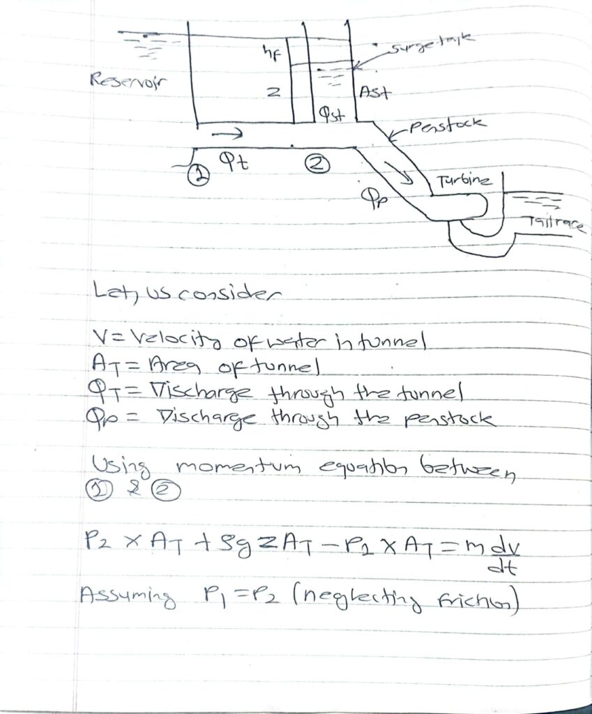
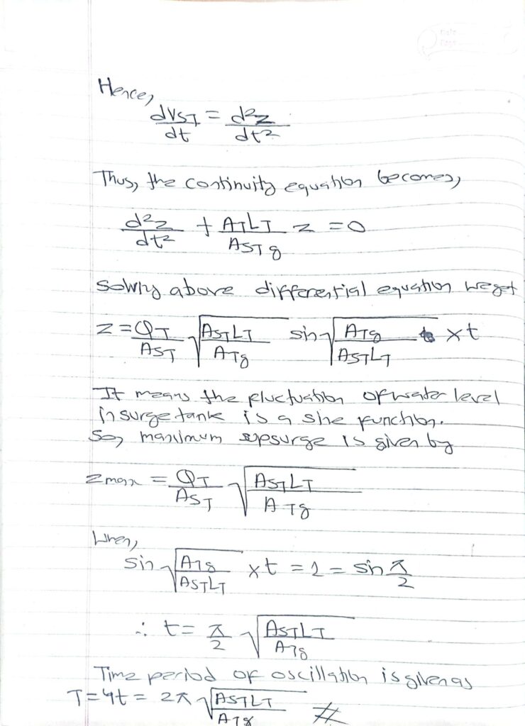
Design of mass oscillation in surge tank:
1.4 Penstock and Pressure shaft
Penstock:
- It is a pipe that conveys the flow from forebay or surge tank to the turbine.
Water hammer:
- It is a pressure surge caused by sudden stop or start of flow of water in pipe.
Cause:
- Power failure.
- Mechanical failure of control device.
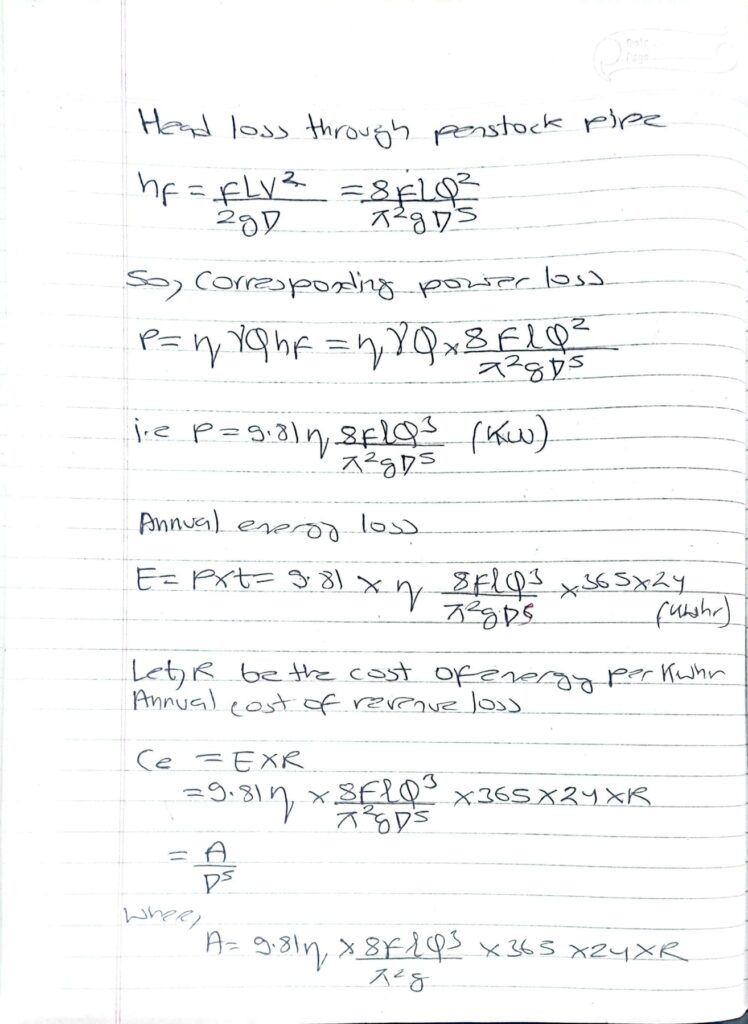
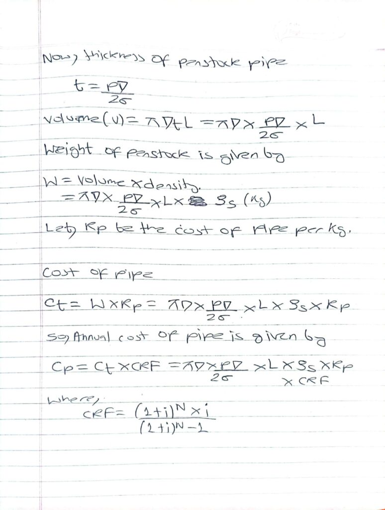
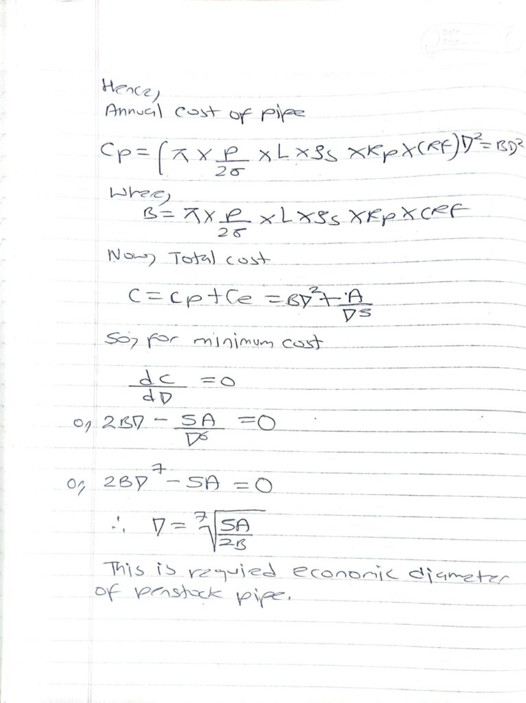
Economic diameter of penstock pipe:
- With the increase of diameter of penstock the head loss decrease as given by Darcy’s formula and hence the revenue loss decreases. At the same time, with the increase in the diameter of the penstock the cost of the pipe increases. Thus, the diameter of the penstock pipe that optimize these two costs is called economic diameter of penstock.
Determination of economic diameter of penstock:

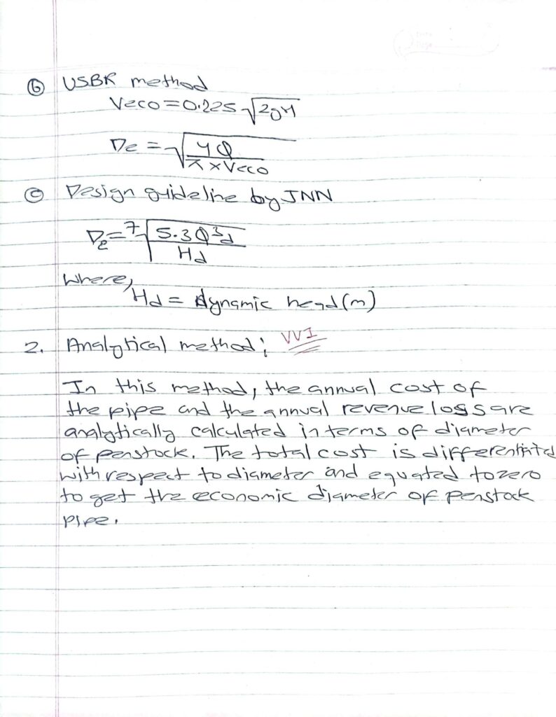
References:
- Dandekar, M. M., & Sharma, K. N. (2010). Water Power Engineering. Vikas Publishing House.
- Punmia, B. C., Pande, B. B. L., Jain, A. K., & Jain, A. K. (2016). Irrigation and Water Power Engineering. Laxmi Publications.
- Singh, Bharat (2018). Fundamentals of Hydrology and Hydropower Engineering. Nem Chand & Bros.
- Central Water Commission, Government of India (2019). Handbook on Hydroelectric Engineering.
- International Energy Agency (IEA) (2021). Hydropower Status Report. Retrieved from www.iea.org
- Nepal Electricity Authority (NEA) (2022). Annual Report on Hydropower Projects in Nepal. Retrieved from www.nea.org.np
- United States Bureau of Reclamation (2020). Design of Small Dams. U.S. Government Printing Office.