
1.1 Classification, general arrangement and layout plan of powerhouse
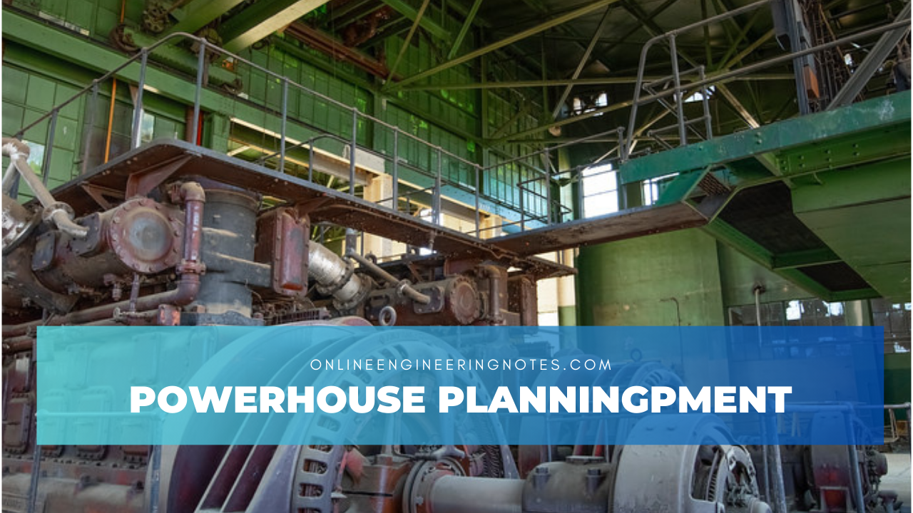
Power house:
- Structural complex where all the equipment for producing and providing electricity are suitably arranged.
Classification of powerhouse:
a. Surface powerhouse:
- Located on the surface of the land so that it has less space restriction.
- Foundation analysis of such structure should be examined carefully.
- If solid bed is not available in surface powerhouse special treatment should be done.
b. Underground powerhouse:
- If there is restriction or not enough space then this powerhouse is constructed.
- Economical.
General arrangement of powerhouse:
1.Superstructure:
- The structure from generator floor to roof of power house.
- Consist of generator, control room, auxiliary equipment needed for ventilation and cooling.
2.Intermediate structure:
- The structure from turbine axis to top of generator.
- Consist of casing, generator and its appurtenances.
- Access to turbine runner.
3.Sub structure:
- Structure that is situated below the axis of turbine.
- Consist of draft tube, tail water channel and galleries.
1.2 General dimension calculation of powerhouse
1.Machine hall (Unit bay)
a. Length:
- The length of machine hall depends upon the number of units, the distance between the units, size of machine and the clearance.
- The standard distance of scroll casing is about 4.5D to 5D.
Where, D= Diameter of turbine
- Minimum clearance is about 2 to 3m.
b. Width:
- Width of machine hall is also determined by the size and clearance space from the walls.
- Width of machine hall can be (5D+2.5)m.
- Width is kept as less as possible.
c. Height:
- Height of machine hall is fixed up by head room requirement of crane operation.
- Generally, 2 to 2.5 m head requirement is for crane operation.
2. Loading Bay:
- It is a space where the heavy vehicle can be loaded and unloaded.
- Dismantled parts of machine can be placed and assembling of equipment is done.
- Load bay floor will have width at least equal to the center distance of machine.
3. Control Bay:
- Main room where equipment like runner, gate valve, generator etc are controlled.
- It may be adjacent to the machine hall as it sends instruction to operation bay.
References:
- Dandekar, M. M., & Sharma, K. N. (2010). Water Power Engineering. Vikas Publishing House.
- Punmia, B. C., Pande, B. B. L., Jain, A. K., & Jain, A. K. (2016). Irrigation and Water Power Engineering. Laxmi Publications.
- Singh, Bharat (2018). Fundamentals of Hydrology and Hydropower Engineering. Nem Chand & Bros.
- Central Water Commission, Government of India (2019). Handbook on Hydroelectric Engineering.
- International Energy Agency (IEA) (2021). Hydropower Status Report. Retrieved from www.iea.org
- Nepal Electricity Authority (NEA) (2022). Annual Report on Hydropower Projects in Nepal. Retrieved from www.nea.org.np
- United States Bureau of Reclamation (2020). Design of Small Dams. U.S. Government Printing Office.