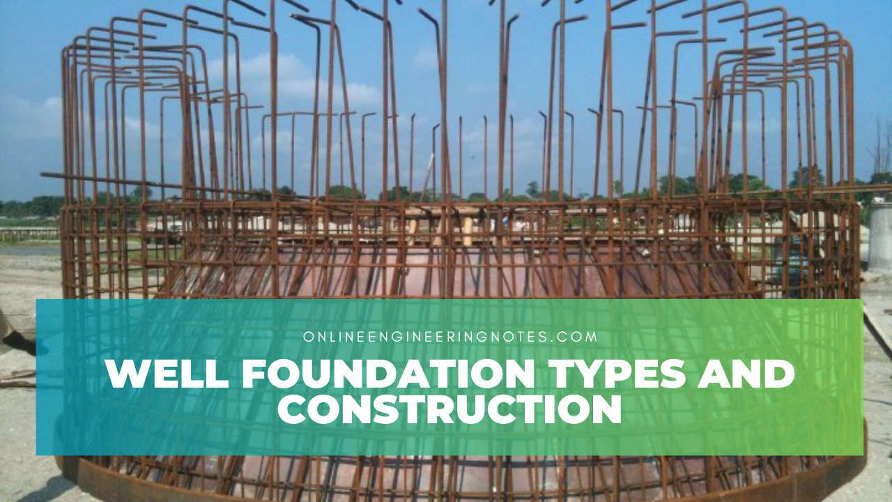
1.1 Introduction, type and shape of well foundation
- Deep foundation provided below water level.
- Also known as caissons foundation.
- Used for bridge construction.
Types of well foundation
1. Open well
- Both top and bottom are open during construction.
- Cost is cheap.
- Rate of progress is slow.
2. Pneumatic caissons
- Open at bottom and closed at top.
- Sunk vertically.
- Construction cost is quite high.
3. Box caissons
- Open at top and closed at bottom.
- Cost of construction is low.
Shape of well foundation
1. Circular well
- Commonly used shape.
- Maximum diameter is 9 m.
2. Doub D-well
- Sunk easily.
- Used for pier.
3. Double octagonal well
- Shape of well is better than double D-well.
4. Twin circular well
- Two indepent wall.
- Small depth of sinking.
5. Rectangular wall
- Used for bridge foundation.
- Large foundation, double rectangular well.
1.2 Component of well foundation
- Well cap: Transmit load of super structure to steining.
- Steining: Transmit load to subsoil.
- Well curb: Facilitates process of sinking.
- Cutting edge: Cuts soil during sinking.
- Bottom plug: Transmit load to sub soil.
- Dredge hole: Hole formed during excavation.
- Top plug: Concrete plug constructed at top.
1.3 Depth of well foundation
- Depth is dependent on:
1. Minimum grip length below scour depth.
2. Base pressure to be within permissible load.
- Normal depth of scour is calculated by lacy’s formula.
d = 0.473 (Q/f)1/2
Where,
Q = Design discharge in cumecs
f = Lacy’s factor = 1.76m1/2
d = Scour depth
m = mean particle size
- Regime width of water way (W)
W = CQ1/2
Where,
W = Regime width
C = Constant
- Actual water way length (L) is less than regime width.
- The actual depth(d|) = d(W/L)0.67
- Grip length: Depth of bottom of well below maximum scour level.
1.4 Force acting on well foundation
- Live load: Load is not constant and change with time.
- Impact load: Sudden load.
- Wind load: Horizontal load.
- Force due to water.
- Seismic force.
- Earth pressure.
1.5 Construction and sinking of well
1. Sinking of a well
Steps:
a. Laying of curb
- If river bed is dry the cutting edge is placed.
- If water table is upt 5 m sand is land is created.
- If water table is more than 5 m more economical curb is built.
b. Construction of well steining
- Steining is constructed with a height of 1.5 m at time of sinking.
c. Sinking operation
- Material is excavated mechanically or manually. Manual work can be done upto 1 m height.
- Well os allowed to remain vertical.
- Sinking in well increase skin friction.
2. Tilt and shift of well
- Objective is to well sunk should sunk straight and vertical.
Cause of tilt and shift:
- No – uniform bearing capacity.
- Obstraction on one side.
- Unequal removal of soil.
Precausion:
- Uniform thickness cutting edge should be provided.
- Tilt and shift should be carefully noted.
Remedial measure of tilt and shift:
1. Control dredging
- Done more on higher side.
2. Eccentric loading
- Provide greater sinking effort on higher side of wall.
3. Pushing the wall
- Applied on lower side of wall.
4. Pulling the wall
- Applied on higher side of wall.
5. Water jetting
- Used for outer face of higher side.
References:
- Terzaghi, Karl, Peck, R.B & John, Wiley (1969) Soil mechanics in engineering practice, New York.
- Arora , K.R (2008), Soil mechanics and foundation engineering, Delhi: Standard Publisher Distribution.

