What is an Op-Amp ?
- Low cost integrating circuit consisting of:
- Transistors
- Resistors
- Capacitors
- Able to amplify a signal due to an external power supply
- Name derives from its use to perform operations on a signal.
Applications of Op-Amps
- Adder
- Subtraction
- Comparators
- Multiplication/ Division
- Integrators
- Differentiators
- Analog to Digital Converters
Pin configuration of op amp

Pin 1 and 5 Offset null — With the 741, you provide the same voltage (signal) to the input pins and adjust the offset null to make sure the output is zero.(common mode)
An ideal op-amp has no offset because its gain is infinite, there are no leakage currents, and there’s no undesired impedance anywhere. Any real op-amp will necessarily have these things, the 741 being no exception
Differential amplifier (pin 2 and 3 input)
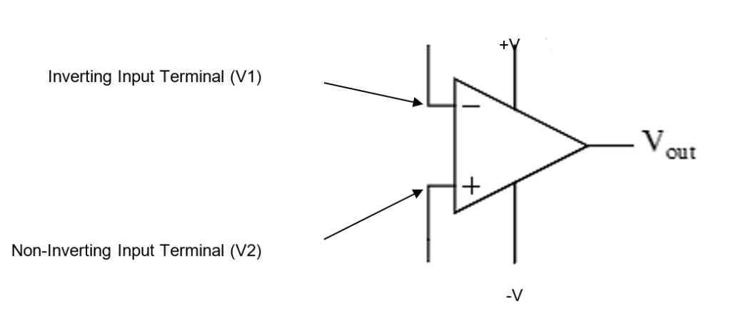
Pin 2– inverting input
Pin 3 – non inverting i/p
Pin 6 – output
Symbol for an Op-Amp
Open loop gain and output voltage of an op-amp
Since input 2 and 3 are out of phase (inverting and non-inverting) they are called differential mode signals. The operational amplifier amplifies the differential mode signals.
Vout = AVOL * VD
Where,
AVOL = open loop voltage gain or simply gain of an op amp
VD = V1-V2 (V1 and V2 are input signals to pin 2 and 3)
Common Mode signals
Input 2 and 3 same magnitude and same phase then output = 0 (common mode signals)
Vout = Avol * Vd
(since v1=v2 thus Vd=0) for common mode
Vout = Avol * 0 = 0
Characteristics of an Ideal Op-Amps
- Infinite input impedance
- Infinite open loop gain (Avol)—typically more than 200000
- Zero output impedance
- Infinite bandwidth
- Common mode rejection ratio = infinite
CMRR = Ad/Acm= Ad/0 = infinite (since Acm for ideal op amp = 0 → CMRR = infinite)
Ad = differential voltage gain Acm = common mode gain
Importance of Common Mode Rejection Ratio (CMRR)
The CMRR is the ability of an op amp (differential amplifier) to reject the common mode signals. The larger the CMRR , the better the op-amp ability at eliminating common mode signals. The common mode signals are usually undesired signals caused by external interferences. (for e.g. RF signals picked up by op-amp inputs).
Configuration of an Op-amp
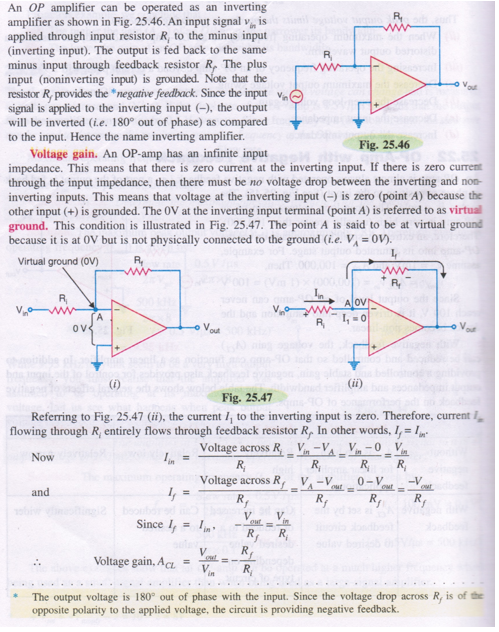
Inverting Configuration
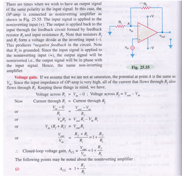
Non-Inverting Configuration
Oscillators
- A clock pendulum is a simple type of mechanical oscillator. Electronic oscillators are used to generate signals in computers, wireless receivers and transmitters, and audio-frequency equipment, particularly music synthesizers.
- An electronic oscillator is an electronic circuit that produces a periodic, oscillating electronic signal, often a sine wave or a square wave. Oscillators convert direct current (DC) from a power supply to an alternating current (AC) signal. They are widely used in many electronic devices
- The oscillator does not create energy, but it acts as an energy converter. It receives d.c. energy and changes it into a.c. energy of desired frequency. The frequency of the oscillations depends upon the constants of the device.
- Common examples of signals generated by oscillators include signals broadcast by radio and television transmitters, clock signals that regulate computers and quartz clocks, and the sounds produced by electronic beepers and video games.
Damped and undamped oscillation

Damped Oscillations:
The electrical oscillations whose amplitude goes on decreasing with time are called damped oscillations.
Undamped Oscillations:
The electrical oscillations whose amplitude remains constant with time are called undamped oscillations.
Barkhausen criteria for undamped oscillation

- The net phase shift around the loop should be 0 or integral multiple of 360 degree. In other words the feedback should be positive.
- The feedback factor or loop gain should be infinite.
Barkhausen’s criterion states that,
It states that if A is the gain of the amplifying element in the circuit and β(jω) is the transfer function of the feedback path
output vo is fed back into its input vin through a feedback network β(jω).
For positive feedback,
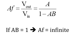
Note : Output offset voltage – Some voltage appears at output even though no input is applied to the opamp , this is known as output offset voltage.
Reference 1 : A reference book basic electronics engineering , Er. Sanjaya Chauwal, G.L Book house Pvt.Ltd.

