

1.1 Soil investigation and soil exploration
Soil investigation:
The process of collecting information about subsurface and taking sample to determine profile of natural soil deposits and engineering properties of soil.
Soil exploration:
The field and laboratory studies carried out for obtaining necessary information about sub soil characteristics including the position of ground water table.
Objective of soil exploration:
- To determine ground water condition in the site.
- To select suitable construction technique.
- To predict and solve potential foundation problem.
- To investigate safety of existing structure.
- To conduct in-situ test to asses appropriate soil characteristics.
Method of soil exploration:
1. Direct method
- It helps to conduct visual inspection of the site locating different strata of the soil and its boundaries.
- It helps to obtain undisturbed sample.
Types of direct method:
a. Test pit
- Depth up to 3 m.
- Uneconomical at greater depth.
- Open type exploration.
b. Trial pits
- Used to recover large bulk sample of soil.
c. Trench
- Used for searching and excavating ancient ruins.
2. Semi-direct method
- Drilling a hole into the soil strata to specified depth is known as boring.
Types of boring:
a. Auger boring
- Trenchless technology used to install steel casing pipe in a variety of soil condition.
b. Auger and shell boring
- Useful in obtaining sample of sand and gravel from below the water table.
c. Wash boring
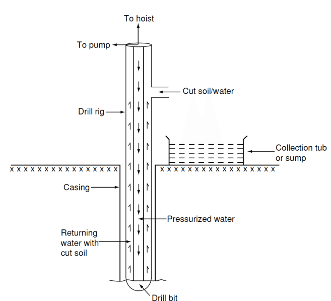
- Simple and fast method of soil exploration for cohesive soil and sand or gravel without boulders.
d. Rotary drilling
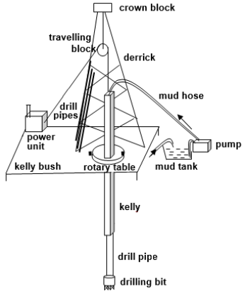
- Used to form a deep observation.
e. Percussion drilling
- Used for making holes in rocks, boulder and hard strata.
3. Indirect method
- It is also known as geophysical method.
- It helps to measure physical properties of soil such as electrical resistive, vibration and gravitational field.
1.2 Soil sampling, types of sample, soil samplers and its basic requirement for cohesive soil
Soil sampling
- Process of extracting soil sample from drilling tools and sampling equipment.
Types of sample:
1. Disturbed sample
- Natural structure of soil gets modified partly or fully during sampling.
a. Non-representative sample
- Sample obtained from auger boring and wash boring.
- Provides information of major change in sub-surface strata.
- Gives rough idea about soil and its stratification.
b. Representative sample
- Suitable for identification and determination of certain physical properties such as Atterberg limit, specific gravity of soil.
2. Undisturbed sample
- Original soil structure is preserved without modification.
- Practically impossible to get undisturbed sample.
- Tube and chunk sample are considered as undisturbed sample.
Types of samplers:
1. Open driven sampler
- Thin walled tube which can be pushed or driven into soil at the bottom of the hole and then rotated to detached the lower end of the sample from the soil.
2. Split spoon sampler
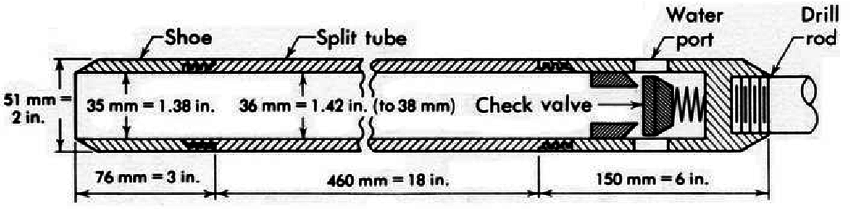
- Used in standard penetration test (SPT).
- It is tube split into two equal halves length wise.
3. Thin wall sampler
- A sampler introduce very less disturbance to the soil sample.
- Used for collecting undisturbed soil sample.
4. Piston sampler
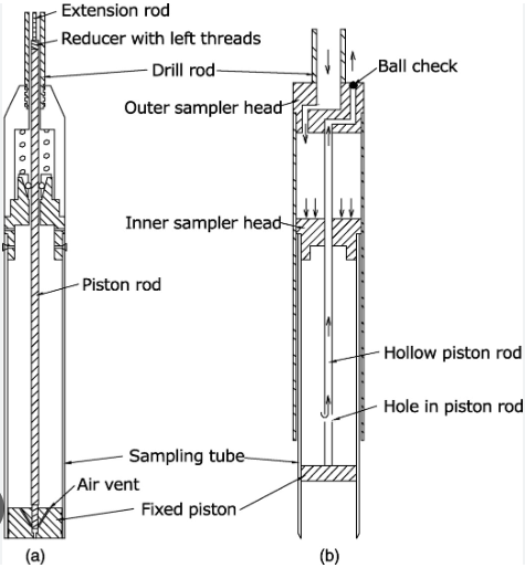
- Special type of thin walled sampler with piston inside.
- Sampling is pushed into the soil hydraulically by keeping the piston stationary.
- Excellent tool for obtaining very fine undisturbed sample.
5. Rotary sampler
- It is a double walled tube sampler with an inner linear removable.
- Sample is collected in inner liner.
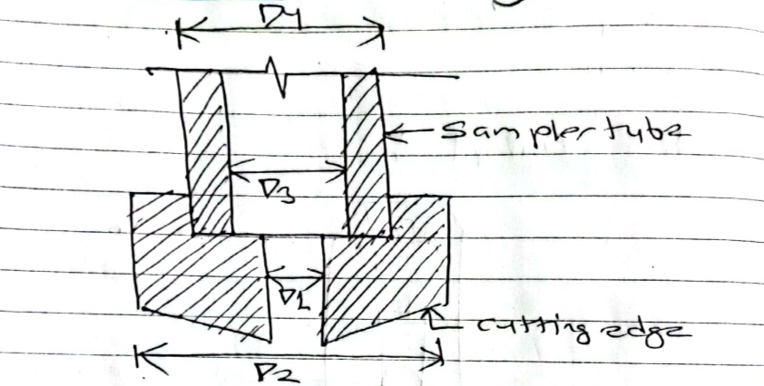
Basic requirement of sampler for cohesive soil:
Let,
D1 = Inner diameter of cutting edge
D2 = Outer diameter of cutting edge
D3 = Inner diameter of sampler tube
D4 = Outer diameter of sampler tube
Basic requirement of sampler for cohesive soil are as follows
1. Area ratio (Ar)
- Ar = (D22 – D12) * 100% / D12
- For obtaining good quality undisturbed sample, the area ratio should be less than 10%.
2. Inside clearance ratio (Ci)
- Ci = (D3 – D1)* 100% / D1
- Reduce the friction between the soil sample and the sampler when soil enters the tube allowing elastic expansion of soil.
- For undisturbed sample: Ci = (0.5 to 3)%
3. Outside clearance ratio (Co)
- Co = (D2 – D4) * 100% / D4
- Lies between (0 to 2)%
- For reducing driving force it must be minimum.
4. Recovery length ratio (Lr)
- Lr = L/H [where, L = Length of sampler & H = Depth of penetration of sampling tube]
- Condition:
- Lr = 1; Indicates a good recovery.
- Lr < 1; Soil in sample is compressed.
- Lr > 1; Soil has swelled.
- It lies between (96 to 98)%
5. Inside wall friction
- Wall of sampler should be smooth and properly oiled.
6. Non – return value
- It should permit easy and quick escape of water and air when sample is driven.
1.3 Planning of exploration, number of bore holes, depth of exploration
Planning of exploration:
- A detailed study of the geographical condition of the area which includes collection of topographical and geographical maps.
- Collection of hydraulic condition such as water table fluctuation, flooding of site.
- Preparation of layout plan of project.
- Preparation of borehole layout plan.
- Marking on the layout plan for addition soil investigation if required.
- Preparation of specification and guideline for field execution.
- Preparation of specification and guideline for testing and collecting sample.
Number of bore holes:
- More number of borehole sunk more we will know about site condition and greater economy is achieved in foundation design.
- For small structure at least 2 or 3 bore holes should be shank.
Depth of exploration:
- Depth of boring depends upon the depth of soil affected by the load transmitted by foundation.
- Guideline regarding depth of boring are :
| Structure | Depth |
| 1. Building | Minimum 10 m |
| 2. Retaining wall | D = 0.5 to 2H |
| 3. Earth dam | D = L |
| 4. Concrete dam | D = 1.5 to 2H |
| 5. Tunnel | D = B |
1.4 Field penetration test and their suitability
1. Standard penetration test
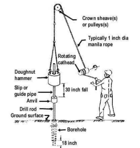
- Most commonly used for cohesion less soil.
- Split spoon sampler is used.
- This test is done to determine relative density.
- The sampler is driven into the soil by dropping hammer into the soil falling vertically through a height of 750 mm at the rate of 30 blows per minute.
- The number of hammer blows required to driven 150 mm of the sampler is counted. Again, the sampler is driven by 150 mm and the number of blows is recorded. Further the sampler is driven by 150 mm and the number blows is recorded.
- The number of blows is recorded for the last two 150 mm interval are added to give the SPT value.
Merit:
- Quick and simple to perform.
- Able to penetrate dense layer, gravel and fill.
Demerit:
- Not continuous.
- Sample obtained is disturbed.
SPT value correction:
a. Dilatancy correction
- Applied when the test is performed in fine or silty saturated sand.
- To reduce over estimate value of SPT.
The correction penetration number;
N|c = 15 + (NR – 15)/2
If NR ≤ 15, Nc = NR
Where,
NR = Recorded N- value
Nc = Corrected N-value
b. Overburden pressure correction
- Penetration resistance of soil depends on over burden pressure.
- In deeper depth overburden pressure is high and its response to SPT test will better compare to the same soil at shallow depth.
Correction SPT- N value is
Nc = CN * N|c
Where,
Nc = Corrected N value of overburden pressure
N|c = Observed N value
CN = Correction factor = 0.77 log10 (2000/ σo)
2. Static cone penetration test (SCPT)
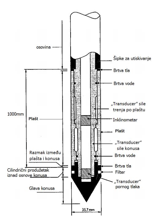
- Widely used in place of SPT test for soft clay and silt.
- Standard cone is pushed into soil by applying force. For obtaining cone resistance cone is pushed downward at a steady rate. Now, both cone and sleeve are pushed into soil and combined resistance is determined.
∴ Resistance of sleeve = Combined resistance – Cone resistance
Merit:
- Simple and quick.
- Economical to perform.
- Help in identifying problem in soil.
Demerit:
- Soil sample is not obtained.
- Requires special equipment and skill manpower.
3. Dynamic cone penetration test (DCPT)
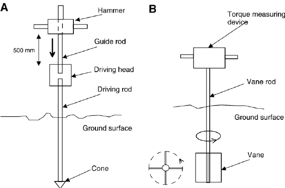
- If hard layer is found DCPT is done.
- The sampler is driven into the soil by dropping hammer into the soil falling vertically through a height of 750 mm at the rate of 30 blows per minute.
- The number of hammer blows required to driven 150 mm of the sampler is counted. Again, the sampler is driven by 150 mm and the number of blows is recorded. Further the sampler is driven by 150 mm and the number blows is recorded.
- The number of blows is recorded for the last two 150 mm interval are added to give the SPT value.
Merit:
- Doesn’t need borehole.
- Economical.
Demerit:
- Cannot be performed in cohesive soil.
- Not possible to determine mechanical properties of soil.
1.5 Ground – water observation
- The variation of ground water affect the soil characteristics such as shear strength.
- Important to find maximum and minimum water level for proper design of structure.
- In highly permeable soil depth of water table is measure by chalk coated tape.
- In low permeable soil depth of water table is measured by Casagrande piezometer.
1.6 Borehole logs
- Detailed record of boring operation and other tests carried out in the field.
- Provided information in bore log is useful to give information of soil type, consistency of soil and water table.
1.7 Site investigation report
- Result/ conclusion of the investigation, exploration and testing program.
- Report should be comprehensive, clear and to the point.
- Typical report includes following point:
- Introduction
- Borehole log
- Field and laboratory test result
- Analysis of data
- Recommendation
- Reference
References:
- Terzaghi, Karl and peck, R.B. John Wiley.(1967). Soil mechanics in engineering practice, New York.
- Arora K.R. (1997). Soil Mechanics and foundation engineering, India: Standard Publisher Distribution.