

Arches
They are very rigid and stable structures which are not considerably affected by movement of their foundations. Arches can be used for large structures made up of materials with negligible tensile strength, such as stones and bricks. Masonry arches of such materials have been used for thousands of years.
Types of Arches
- Arches may be classified on the basis of materials of which they are built, steel and reinforced concrete is the most common of all the materials.
- On the basis of form, arches may be further classified as parabolic, circular, elliptical etc.
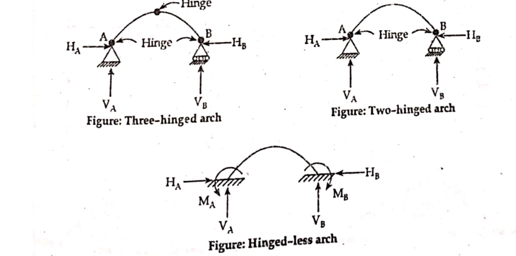
- From the point of view of structural behavior arches are conveniently classified as:
- Three-hinged arch
- Two-hinged arch
- Hinge less(fixed) arch
Structurally
- A three hinged arch is statically determinate. There are four unknowns and there are three equations of equilibrium and one condition equation. (Moment at the third hinge is zero.)
- The two hinged arch is statically indeterminate to the first degree: there are four unknowns and three equations of static equilibrium.
- The hinge less arch is statically indeterminate to the third degree as there are six unknowns and only three equations of equilibrium.
Comparison between Arch and Cable
- While a cable is a tension member, arch behaves in a reverse fashion and it is basically a compression member.
- A cable is flexible and its shape with different types and positions of loads. It cannot resist any bending moment hence moment everywhere is zero.
- On the other hand, an arch is a rigid structure. It cannot change its shape corresponding to different types of loadings. Hence, through primarily it is a compression member it is often subjected to bending moment and shear through small magnitude.
Efficiency of an Arch
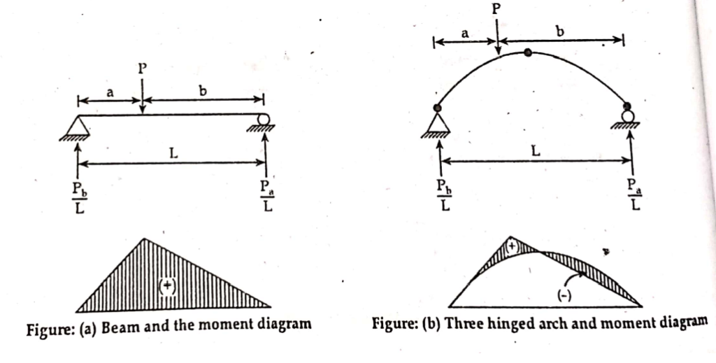
- The efficiency of an arch can be demonstrated by comparing it with beam of the same span under same loading.
- The arch resists the load by developing vertical as well as horizontal components of reaction. The horizontal reaction component reduces the moment from that in a simple beam.
- An arch supports loading with much less moment than a corresponding straight beam.
- It must be remembered that the reduction in moment is achieved at the expense of large axial compression in the arch rib and also horizontal reaction components at the springing.
- The moment diagrams are shown below:
Three Hinged Arch with Support at Same Level
1. Parabolic Arch
- For origin at A
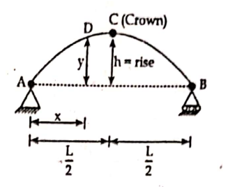
y= kx(L-x) ————————-(1)
At x= L/2 and y=h
We have,
h= k.L/2 (L- L/2)
or, k = 4L/ L2
∴ y = (4hx/L2 )*(L-x)
This is equation of parabola with origin at A.
- For origin at C
If origin is at C, the equation parabola is
x2 = ay————————- (2)
At x = L/2 and y=h
We have,
a= L2/4h
∴ y = (4h/L2 )*(x2)
2. Circular arch
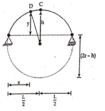
Here, R is the radius of circular arch and D is any point on arch having co-ordinate (x, y).
Using property of circle, we have,
L/2 * L/2 = h (2R-h)
∴ R = (L2/8h)+h/2
Co-ordinate of point D is given by;
x= L/2 – Rsinθ
y= Rcosθ – (R-h)
Three Hinge Arch with Support at Different Level
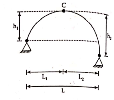
If origin is at C; the equation of parabola is
x2/y = Consatant
or x/(y)1/2 = Constant
Here,
L= L1+L2
or, L1/(h1)1/2 = L2/(h2)1/2
or, L2 = (h2/h1)1/2* L1
and L1 = (L*h11/2) / (h11/2+ h21/2)
∴ L2 = (L*h21/2) / (h11/2+ h21/2)
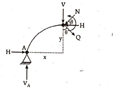
Analysis of Three Hinged Arch
- Determination of support reactions
ΣFx =0
ΣFy =0
ΣMA =0 or ΣMB =0( all loads)
ΣMC =0 ( Considering only left or only right part)
- Determination of radial shear (Q), normal thrust (N) and bending moment ( M)
Here, θ is the angle mode by normal thrust with horizontal,
Normal thrust (N) = Vsinθ + Hcosθ
Radial shear (Q) = Vcosθ – Hsinθ
Bending moment at D = Beam moment – HyD
Analysis of Three-Hinged Arch by the Graphical Method
The figure below shows a three hinged arch subjected to a load system. Let, VA and VB be the vertical reaction at the support A and B. Let, H be horizontal thrust. Let pq, qr and rs represents the loads w1,w2,w3. On this load line, let m be a point such that mp represents the vertical reaction VA and ms represent vertical horizontal thrust.
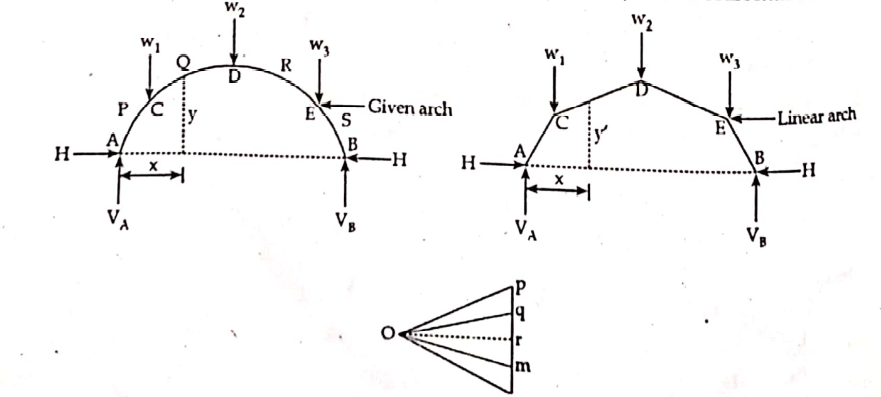
The structure ACDEB is called linear arch or theoretical arch.
It can be easily realized that the shape of the linear arch follows the shape of the free bending moment diagram for a beam of the same span and subjected to same loading.
Free B.M. at any section X = Polar distance ( mo) * y! = Hy!
Moment due to horizontal thrust = Hy!
Where, y and y! are the ordinates of the given and linear arch respectively.
Net B.M. at section X = Hy- Hy! = H(y- y!)
∴Net B.M. at section X is proportional to (y- y!)
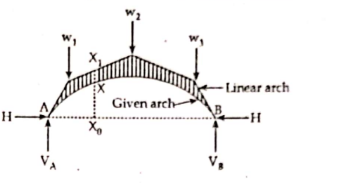
Hence, the B.M. at any section of an arch is proportional to the ordinate or the intercept between the given arch and the linear arch. The is called Eddy’s theorem.
The actual bending moment at section X is proportional ordinate XX1.
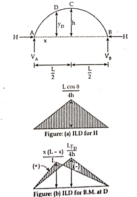
Influence Line Diagram for Three Hinged Arches
I.L.D for three hinged arches are given below:
- Horizontal reaction (H)
- Bending moment (B.M.)
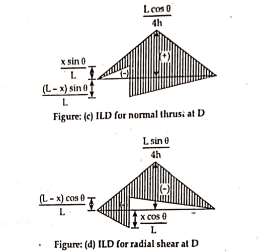
- Normal thrust
- Radial shear
Maximum Bending Moment Diagrams in Three Hinged Parabolic Arch
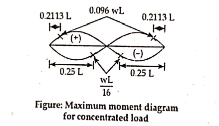
- When a concentrated load moves
The maximum positive moment occurs at a distance of 0.2113 L from either end and has value of 0.096wL, where w is concentrated load and L is total span of arch. The maximum negative moment occurs at a distance of 0.25L from either end and has the value of wL/16.
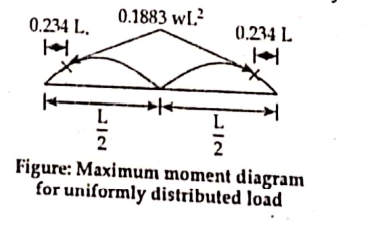
- When a uniformly distributed load moves
The maximum positive or maximum negative moment occurs at a distance of 0.234L and has value of 0.01883wL3, where w is uniformly distributed load.
References: 1. Theory of Structure I, Dr. Kamal Bahadur Thapa