
Cable
Cables are slender, flexible members made of a group of high-strength steel wires twisted together mechanically. Steel cables provide the simplest means for supporting loads.
Steel cables, which are economically manufactured from high-strength steel wire, have an ultimate tensile strength of approximately 1862 MPa. The wires of cables are formed by drawing the alloyed steel bars through dies. This process aligns the molecules of the metal so that wires with tensile strength reaching as high as 1862 MPa can be produced. A group of such high strength steel wires twisted together forming a strand are used to make the cables. The modulus of elasticity of steel cables is approximately equal to 179 GPa, which is lower than the modulus of elasticity of steel cable is approximately equal to 179 GPa, which is lower than the modulus of elasticity of structural steel bars (200 GPa). Steel cables are easily handled and placed in position, even for very long spans. They provide lowest cost-to-strength ratio of any common structural members. The self-weight of the cable is generally neglected.
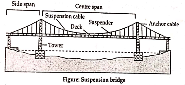
Element of Suspension Bridge
Suspension bridges are used for highways, where the span of bridge is more than 200m. Basically, a suspension bridges consists of following elements:
- Cable
- Suspenders
- Decking including the stiffening girder
- Supporting tower
- Anchorage
- Windguy and Windties
- Anchorage
A typical suspension bridge and its components are shown below:
Equilibrium of Light Cable: General Cable Theorem
Let us consider general case of cable supported at two supports A and B, which are not at the same level. The cable is acted by the system of vertical forces i.e. P1,P2,P3…Pn as shown in figure below.
Let L be the horizontal span of cable and α be the inclination of line AB, with the horizontal. Obviously the differences in elevation between two supports A and B is equal to Ltanα.
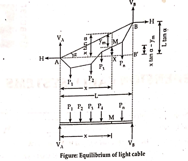
Let VA and VB be the vertical components of reactions at A and B. Since there is no horizontal loading on the cable, the horizontal reaction(H) at ends A and B will be equal in magnitude but opposite in direction.
In order to find vertical reaction VA, take moments about B;
-VA * L – H tanα + ΣMB = 0
∴ VA = (ΣMB/L)- H tanα ——————————————(1)
Where, ΣMB = Sum of moments of all loads
P1,P2,….Pn about B.
Consider any point M of horizontal distance x from A.
Assume that the cable is perfectly flexible so that the bending moment at any point on the cable is zero.
Now,taking moment of all forces to the left point of M is zero.
H*(xtanα – ym) + VAy * x – ΣMm = 0
Substituting value of VA from equation(1); we get,
H*xtanα – H*ym+ x/L * ΣMB – H*xtanα– ΣMm = 0
or, H*ym = x*( ΣMB/L) – ΣMm
Also, from beam; we have,
ΣMB=0
or, VA*L- ΣMB = 0
∴ VA = (ΣMB / L )
∴ Hym = VA * x – ΣMm
Where, Hym = Beam moment at M.
It states that at any point on the cable acted by vertical loads, the product of H and ym ( vertical distance from that point to the cable curve) equal to the bending moment at same point M considering simply supported beam of same span and same loading at that of cable.
Cable Subjected To Uniformly Distributed Load and Its Equation: At Same Level
Let us consider a cable subjected to a uniformly distributed load of w per unit run on the horizontal span.
Let, L= Length of cable ( curve length )
l = Span of cable ( horizontal length )
VA = Vertical reaction at support A
VB = Vertical reaction at support B
h = Central deflection
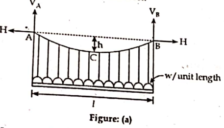

Now, vertical reaction VA and VB are equal.
VA = VB = wl/2
Taking moment about right of C; we have,
ΣMC = 0
or, VB * l/2 – H* h – w*l/2 *l*4 =0
or, H *h = wl/2 * l/2 – wl2/8
∴ H = wl2/8
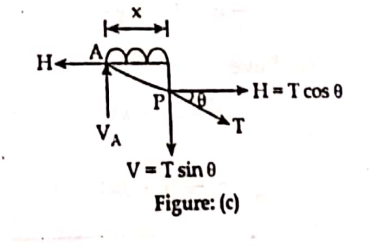
Let, T be the tension at any point P of the cable. Cosider the section (i)-(i) at distance x from support A.
Let, θ be the inclination of the tangent at with the horizontal.
Now,
Tension(T) = (V2+H2)1/2
But, Vmax= wl/2 = VA = VB
∴ Tmax= {(wl/2)2 + ( wl2/8h)2}1/2 = wl/2 * { 1 + l2 /16h2}1/2
i.e. tension is maximum at supports since vertical reaction (V) is maximum at support and H is constant throughout the cable.
Similarly, tension ( T) is minimum at point of maximum sag because “ V” is minimum at mid span i.e. V = 0
∴ Tmin = (0 + H2)1/2 =H
To get equation of cable
Applying equation of equilibrium on left portion of section (I)-(I); we get,
ΣFx = 0 gives;
H= Tcosθ —————(1)
Also,
ΣFy = 0 gives;
VA = wx + Tsinθ
∴ Tsinθ = VA – wx —————(2)
Dividing equation (2) by equation (1); we get,
tanθ = (wA – wB) / H
or, dy/dx = 1/H {wlx/2 – wx2/2} = wx(l-x)/2h
Substituting value of H; we get,
y= {(wx)/ (2* wl2/8h) } * (l-x)
Substituting value of H; we get,
y= {(wx)/ (2* wl2/8h) } * (l-x)
∴ y = 4hx*(l-x)/ l2 ; which is equation of parabola.
Thus,shape of cable is parabola.
To find the length of cable
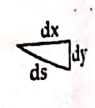
ds = {(dx)2 + (dy)2}1/2 = {1+ (dy/dx)2}1/2 dx
∴ ds/dx = {1+ (dy/dx)2}1/2
We have,
y= 4hx(l-x)/l2
∴ dy/dx = 4h*(l-2x)/l2
∴ ds/dx = {1+ ([dy/dx][l-2x])2}1/2
( Neglecting the other term of expansion)
Now,
Curve length ( L) = ∫ds
Determination of the Horizontal and Vertical Reaction of Cable with Ends at Different Level Carrying Uniformly Distributed Load.

Consider cable ACB supported at different levels A and B and C is the lowest point carrying uniformly distributed load w/ unit length.
The point C is extended to A! and B! as shown by dotted lines such that AC = A!C dip of h2.
Let, the horizontal distance between A and C = l1
And Horizontal distance between B and C = l2
Now, we have;
l1 + l2 = l ————————-(1)
Considering AA!
H= wl2/8h = wl12/ 8h1 —————–(2)
Considering BB!
H= wl2/8h = wl22/8h2 ——————–(3)
Equating equations (2) and (3) ; we get
wl12/8h1 = wl22/8h2
l12 = h1/h2 * l22
∴ l1/l2 = (h1/h2)1/2 ————————(4)
Also,
Length of cable ACA’ (S1) = 2l1 +8h12 /(3*2l1) =2l1+4h12/3l1
And,
Length of cable BCB’ (S2) = 2l2+8h22 /(3*2l2) =2l2+4h22/3l2
∴ Actual length of cable (S) = S1/2+ S2/2
∴ S = l + 2h12/3l1 + 2h22/3l2
To determine H
We have,
l= l1+l2 = l1+l2*( h2/h1)1/2 { From equation(4)}
∴ l1 = [l*(h1)1/2]/[(h1)1/2+(h2)1/2]
Substituting value l1 in equation (2); we get
H= (w/2h1)* [l*(h1)1/2]/[(h1)1/2+(h2)1/2] = wl2/[(h1)1/2+(h2)1/2]
Which is required expression for horizontal reaction.
To find vertical reactions
Let,
VA= Vertical reaction at support A
VB= Vertical reaction at support B
Now, taking moment about C of the forces on the left sides of C;we get,
VA*l1 = H*h1+ wl12/2
or, VA= H*h1/l1 +( wl12/2) * 1/l1
Putting value of H in above equation;we get,
VA= wl1
∴ VA= wl1
Similarly, taking moment about C of the forces on right sides of C; we get,
VB*l2 = H*h2+ wl22/2
or, VB= H*h2/l2 +( wl22/2) * 1/l2
Putting value of H in above equation;we get,
VB= wl2
∴ VB= wl2
Suspension Bridge with Three-Hinged Stiffening Girder
When suspension bridge is subjected to a moving (or rolling) load system the funicular polygon will change its shape and hence the shape of cable is also change.
In suspension cable bridge it is necessary to maintain the parabolic shape of cable to satisfy this condition the load transmitted to the cable should be uniformly distributed load.
This is achieved by either two hinged or three hinged stiffening girder.
The main purpose of providing these stiffness girders is to reduce the sag under the rolling load.
The girders are suspended form cables through hanger cables.Hence, the uniformly distributed dead load of the roadway and stiffening girders is transmitted to the cables through hanger cables and is taken up entirely by the tension in the cables. The stiffening girder does not suffer any S.F. or B.M. under dead load as girder is supported by closely spaced hanger cables throughout.
Any live load on the bridge will be transmitted to the girders as point loads. The stiffening girders transmit the live load to the cable as uniformly distributed load. While doing so the stiffening girders will be subjected to S.F. and B.M. throughout their length.
Extra:
1. Explain with neat sketches tower structure as well as wind cables and windguy.
Ans. Suspension bridges are often supported on towers. Towers provide means for the cable to change the direction. Normally three type of towers are used in suspension bridge system.
a. Tower with saddles
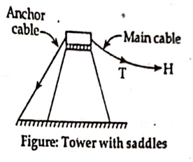
- Such types of tower are fixed at their bases and support the main cable through a carriage, which is free to roll horizontally on the tower top.
- In this arrangement, the two cables does not need to have same tension.
b. Tower with pulley at top

- Such type of tower acts like vertical cantilevers and offer some resistance to cable.
- Assuming pulley as frictionless, tension in anchor cable is taken as same as tension in the main cable.
c. Tower hinged at base

- Such types of towers are free to rock in the plane of the main cables, which are securely attached to the tower tops.
- Suspension bridges are necessary to be protected from the vibration caused by wind. The lateral stability of the bridge is thus achieved by windguy arrangement. A standard form of windguy arrangement is shown in figure.
- It essentially consists of the bridge with a cable in the lateral direction with parabolic shape.
References: 1. Theory of Structure I, Dr. Kamal Bahadur Thapa