
Total Station and Its Application
A total station (TS) or total station theodolite (TST) is an electronic/optical instrument used for surveying and building construction. It is an electronic transit theodolite integrated with electronic distance measurement (EDM) to measure both vertical and horizontal angles and the slope distance from the instrument to a particular point and on board computer to collect data and perform triangulation calculations.
Components of a Total Station

- EDM
- Prisms
- Electronic theodolite
- On-board microprocessor
- Data collector ( built in or separate unit )
- Data storage ( internal or memory card)
Operation of Total Station
- Distance Measurement
Electronic distance measurement (EDM) instrument is a major part of total station. Its range varies from 2.8 km to 4.2 km. The accuracy of measurement varies from 5mm to 10 mm per km. They are used with automatic target recognizer. The distance measured is always sloping distance from instrument to the object.
- Angle Measurement
The angle theodolite part of total station is used for measuring vertical and horizontal angle. For measurement of horizontal angles, any convenient direction may be taken as reference direction. For vertical angle measurement, vertical upward (zenith) direction is taken as reference direction. The accuracy of angle measurement varies from 2 to 6 seconds.
- Data processing
The instrument is provided with an inbuilt microprocessor. The microprocessor averages multiple observations. With the help of slope distance and vertical and horizontal angles measured, when height of axis of instrument and targets are supplied, the microprocessor computers the horizontal distance and X, Y, Z coordinates. The processor is capable of applying temperature and pressure corrections to the measurement, if atmospheric temperature and pressure are supplied.
- Display
Electronic display unit is capable of displaying various values when respective keys are pressed. The system is capable of displaying horizontal distance, vertical distance, horizontal and vertical angles, difference in elevations of two observed points and all the three coordinate of the observed points.
- Electronic Book
Each point data can be stored in an electronic note book (like compact disc). The capacity of electronic note book varies from 3000 points to 4000 points data. Surveyor can upload the data stored in note to computer and reuse the note book.
Application of Total Station
Total stations are mainly used by land surveyors and civil engineers, either to record features as in topographic surveying or to set features ( such as road, houses or boundaries). They are also used by archaeologists to record excavations and by police, crime scene investigators, and private accident re-constructionist and insurance companies to take measurements of scenes.
- Mining
Total stations are the primary survey instrument used in mining surveying. A total station is used to record the absolute location of the tunnel walls, ceilings (backs) and floors as the drifts of an underground mine are driven. The recorded data are then downloaded into a CAD program and compared to the designed layout of the tunnel. The survey parts installs control station at regular intervals. These are small steel plugs installed in pairs in holes drilled into walls or the back. For wall stations, two plugs are installed in opposite walls, forming a line perpendicular to the drift. For back stations, two plugs are installed in the back forming a line parallel to the drift.
A set of plugs can be used to locate the total station set up in a drift or tunnel by processing measurements to the plugs by intersection and resection.
- Mechanical and Electrical Construction
Total stations have become the highest standard for most forms of construction layout. They are most often used in X and Y axis to layout the locations of penetration out of the underground utilities into the foundation, between floors of a structure as well as roofing penetrations.
- Meteorology
Meteorologists also use total stations to track weather balloons for determining upper-level winds. With the average ascent rate of the weather balloon known as assumed, the change in azimuth and elevation readings provided by the total stations as it tracks the weather balloon over time are used to compute the wind speed and direction at different altitudes. Additionally, the total station is used to track ceiling balloons to determine the height of cloud layers. Such upper level wind data is often used for aviation weather forecasting and rocket launches.
Application of Total Station in Civil Engineering
- To obtain the horizontal distance, inclined distance and vertical distance between these points.
- To find the length of a missing line.
- To locate the points at a predetermined distance along gridlines.
- To get the three dimensional coordinates of a point in space.
- To find the elevation of the remote object.
- To measure horizontal and vertical angles.
Use of EDM IN Surveying
Electronic distance measurement (EDM) is a method of determining the length between two points using phase changes that occur as electromagnetic energy waves travel from one end of the line to the other end. Electronic distance measurement in general is a term used as a method for distance measurement by electronic means. In this method, instruments are used to measure distance that rely on propagation, reflection and reception of electromagnetic waves like radio, visible light or infrared waves.
EDM instrument are classified based on the type of carrier wave as:
- Microwave instruments
- Light wave instruments
- Infrared wave instruments
Operations of Electronic Distance Measurement Instruments
The electromagnetic waves propagate through the atmosphere based on the equation;
V= f λ = (1/T) λ
Where, V is the velocity of electromagnetic energy in m/sec
f is the modulated frequency in Hz
λ is the wavelength measured in meters.
T is the time in seconds = 1/f
Mainly the waves that are propagated can be represented like a sine wave as shown in figure below.
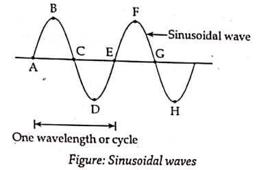
Another property of wave called as phase of wave Φ, is very convenient method of small fraction of wavelength during measurment of EDM. The points A,B, C, D etc. represents various phase points.
| Point | A | B | C | D | E | F | G | H |
| Phase, Φ | 0° | 90° | 180° | 270° | 360° (or 0° ) | 90° | 180° | 270° |
Say AB is the survey line to be measured, having a length of D. The EDM equipment is placed at ends A and B. A transmitter is placed at A and a receiver is placed at B. The transmitter lets propagation of electromagnetic waves towards B. A timer is also placed. At the instant of transmission of wave from A, the timer at B starts and stops at the instant of reception of incoming wave at B. This enable us to known the transmit time for the wave from the point A to B.
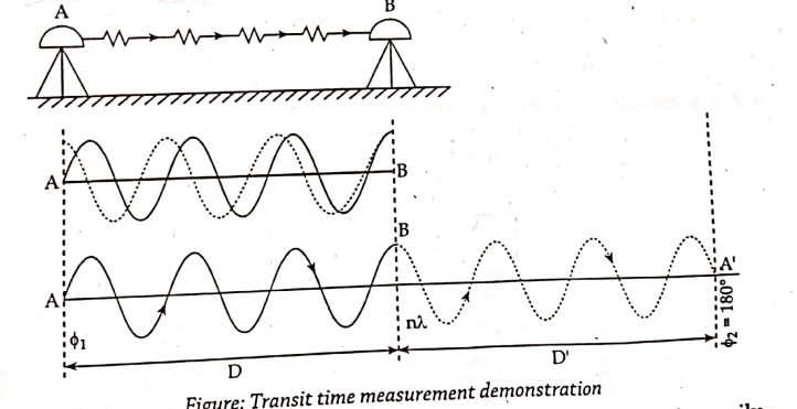
From the transit time and known velocity, the distance can be easily measured. Now to solve the problem arise due to difficulty in starting the timer at B, a reflector can be placed as shown below instead of a receiver at B.
Let the waves get transmitted from A and reflected from B. If the received signal is out of phase by a measure of △Φ, then equivalent distance is;

d= △Φ * λ/360°
Thus, the distance,
D= ½ { n λ + (△Φ * λ/360° ) }
Where, n is the integral number of wavelength, λ in the double path.

Schematic Diagram of EDM System

Application of EDM to Civil Engineering and Surveying
Generally, the use of EDM in engineering surveying operation results in a saving in time and in most case, an improvement in the accuracy of distance measurment when compared with taping and with optical methods.
When using EDM, rapid and accurate surveying of detail is possible owing to the long ranges attainable and fewer control stations are required.Consequently, EDM has replaced tacheometric methods and chain surveying for the production of site plans. In addition, both the combined theodolite/EDM and electronic tacheometer systems are extremely well adapted to forming digital terrain models and if data storage units are used these can be interfaced directly with the computer forming the model.
As angles and distances can be measured simultaneously with the latest infrared short-range equipment, many setting out operations are now simplified. Some instruments have a continuous readout facility and this enables distances of many hundred of meters to be set out in one sighting often over ground that would be unsuitable for taping. The ability to take measurements across congested sites is also a great advantage.
In road works, EDM can be used to coordinate the major control points for the initila survey of the route and then can use these stations to establish the road centerline by polar methods rather than tangential angle methods. Another instance of changing techniques is that buildings can be set out from two or more instrument stations by polar coordinates rather than by using a theodolite to establish right angles at each other.
These methods have been helped by the advent of advanced pocket calculators and computers and many local authorities now issue contractors with a computer printout for setting out engineering works in the form of bearing and distance tables.
A further use of EDM in civil engineering is in tunneling where it is used in the surveying necessary for the establishment of headings at ground level and for the measurement of the depths of shafts. EDM has also been used successfully for positioning piles and other inshore marine structures.
Strain Gauze Load Cell
A load cell is a transducer tha is used to create an electrical signal whose magnitude is directly proportional to the force being measured.
Basic Principle of Strain Gauge Load Cell
When steel cylinder is subjected to a force, it tends to change in dimension. On this cylinder, if the strain gauges are bounded, the strain gauge also gets streched or compressed causing a change in its length and diameter. This change in dimension of the strain gauge causes its resistance to change. This change in resistance or output voltage of the strain gauge becomes a measure of applied force.
Construction
They are a cylinder made up of steel on which four identical strain gauge are mounted and out of four strain gauge, two of them ( R1 and R4) are mounted along the direction of the applied load ( vertical gauges). The other two strain gauges ( R2 and R3) are mounted circumferentially at right angles to gauges R1 and R4. The four resistance strain gauges are connected electrically as a four arms of wheatstone bridge. The circuit diagram of wheatstone bridge is also shown below.

Case I
When there is no load (force) on the steel cylinder, all the four gauge will have the same resistance. As the terminals N and P are at the same potential, the wheatstone bridge is balanced and hence the output voltage will be zero.
Case II
Now, the load ( force) to be measured ( say compression force) is applied on the steel cylinder. Due to this, the vertical gauges R1 and R4 will undergo compression and hence there will be decrease in resistance. At the same time, the horizontal gauges R2 and R3 will undergo tension and there will be an increase in resistance. Thus, when strained, the resistance of the various gauges change.
Now, the terminal N and P will be at different potential and the change in output voltage due to the applied force becomes a measure of the applied force when calibrated.
Uses of Strain Gauge Load Cells
- They are used for weighting purposes.
- They are used for material testing in process industry.
- They are used in tensile test machines as a major component.
- They are used for both expansion and compression.
Remote Control Sensing and Robotics
Remote sensing is the science of acquiring information about earth’s surface without actually being in contact with it. This is done by sensing and recording reflected or emitted energy and processing, analyzing and applying that information. Human apply remote sensing in their day to day business, throught vision, hearing and sense of smell. The data collected can be of many forms; variations in acoustic wave distributions (e.g. sonar), variations in force distributions (e.g. gravity meter), variations in electromagnetic energy distributions (e.g. eye) etc. These remotely collected data through various sensors may be analyzed to obtain information about the objects or features under investigation.
Thus, remote sensing is the process of inferring surface parameters from measurement of the electromagnetic radiation (EMR) form the earth’s surface. This EMR can either be reflected or emitted from the earth’s surface. This EMR can either be reflected or emitted form the earth’s surface. In other words, remote sensing is detecting and measuring electromagnetic (EM) energy emanating or reflected from distant objects made of various materials so that we can identify and categorize these objects by class or type, substance and spatial distribution.
Remote sensing provides a means of observing large areas at finer spatial and temporal frequencies. It finds extensive applications in civil engineering watershed studies, hydrological states and fluxes simulations, hydrological modeling, disaster mangaement services such as flood and drought warning and monitoring, damage assessment in case of natural calamities, environmental monitoring, urban planning, etc.
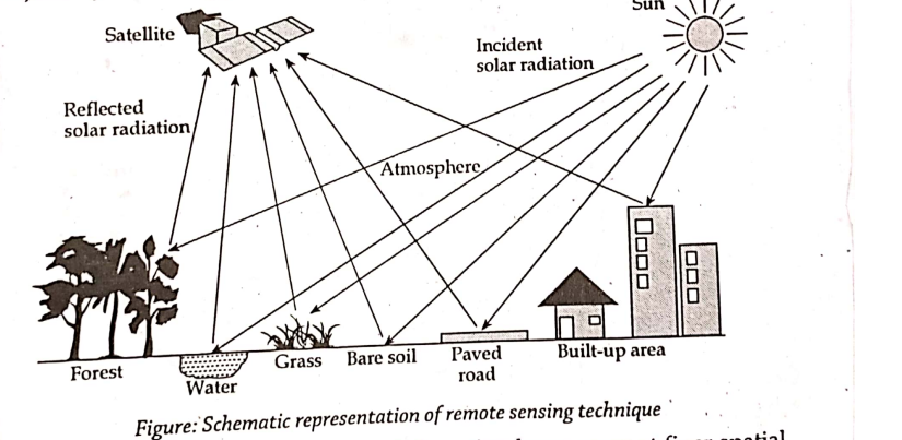
Principle of Remote Control Sensing
Different objects reflect or emit different amounts of energy in different bands of the electromagnetic spectrum. The amounts of energy reflected or emitted depends on the properties of both the materials and the incident energy (angle of incidence, intensity and wavelength). Detection and discrimination of objects or surface features is done through the uniqueness of the reflected or emitted electromagnetic radiation from the object.
A device to detect this reflected or emitted electro-magnetic radiation from an object is called sensor. A vehicle used to carry the sensor is called a platform ( e.g. aircrafts and satellites).
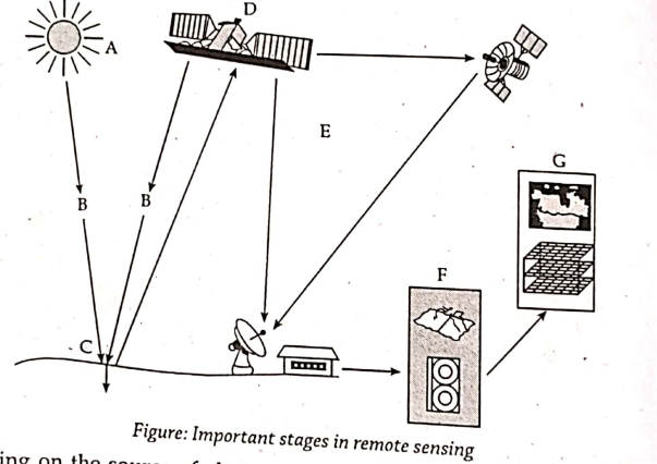
The main stages in remote sensing are as follows:
- Emission of electromagnetic radiation
The sun or an EMR source located on the platform
- Transmission of energy from the source to the object
Absorption and scattering of the EMR while transmission.
- Interaction of EMR with the object and subsequent reflection and emission
- Transmission of energy from the object to the sensor
- Recording of energy by the sensor
- Transmission of the recorded information to the ground station
- Processing of the data into digital or hard copy image
- Analysis of data
Depending on the source of electromagnetic energy, remote sensing can be classified as passive or active remote sensing.
- Passive Remote Sensing
In case of passive remote sensing source of energy is the naturally available such as the sun. Most of the remote sensing of EMR. Solar energy reflected by the targets at specific wavelength bands are recorded using sensors onboard air-borne or space borne platforms. In order to ensure ample signal strength received at the sensor, wavelength (energy bands capable of traversing through the atmospheric interaction are generally used in remote sensing. Passive sensors can also be used to measure the earth’s radiance but they are not very popular as the energy content is very low.
- Active Remote Sensing
In case of active remote sensing, energy is generated and sent from the remote sensing platform towards the target. The energy reflected back from the targets are recorded using sensors onboard the remote sensing platform. Most of the microwave remote sensing is taking a picture with camera having built-in flash.

Advantage of remote sensing
- Provide data of large areas.
- Rapid production of maps for interpretation.
- Easy and rapid collection of data.
- Relatively inexpensive when compared to employing a team of surveyours.
- Able to obtain imagery of any area over a continous period of time through which any anthropogenic or natural changes in the landscape can be analyzed.
- Provides data of very remote and inaccessible regions.
Disadvantages of remote sensing
- Objects can be misclassified or confused
- Data from multiple source may create confusion.
- Needs cross verification with grounds (field) survey data.
- The interpretation of imagery required a certain skill level.
- Distortion may occur in an image due to the relative motion of sensor and source.
Reference 1 : A reference book basic electronics engineering , Er. Sanjaya Chauwal, G.L Book house Pvt.Ltd.