
Moving static loads
Structure which is used in bridges, gantry girders, crane beams etc. are subjected to loads which change their position often such loads are called moving static loads.
Few standard loads are:
- Single concentrated load
- U.D.L greater than the span
- U.D.L smaller than the span
- Two concentrated load with specified distance between them
- Multiple concentrated loads(train of wheel loads)
Influence Line Diagram(I.L.D)
It is a curve the ordinate to which at point equal to the value of some particular function due to a unit load acting at that point. The function may be support reaction, shear force or bending moment.
Note:
I.L.D is always drawn for a concentrated unit load and it is independent of any type or system of loading.
Use of I.L.D in Civil Engineering:
- To determine the structural quantity( Like reaction, shear force, bending moment) for a given system of load on the span of the structure.
- To determine the position of like load system to have the maximum value of structural quantity.
Advantage of I.L.D:
- It is a useful tool for dealing with moving loads.
- It is a method of speedy determination of the value of structural quantity at any section under any complex system of loading.
Difference between I.L.D and B.M.D or S.F.D.
The ordinate of B.M.D or S.F.D gives the value of B.M or S.F. at the section where the ordinate has been drawn whereas the ordinate of I.L.D at any point gives the value of B.M. of S.F at the given section for which the I.L.D has been drawn and not at the point at which the ordinate has been drawn.
I.L.D for beams:
- Simple supported beam
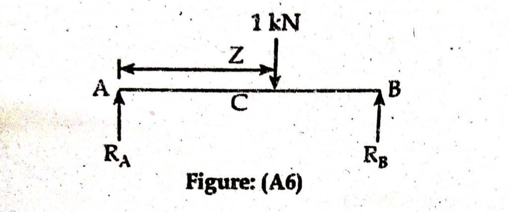
Consider a simply supported beam as below. Let unit load rolls from left to right.
Calculation of relations

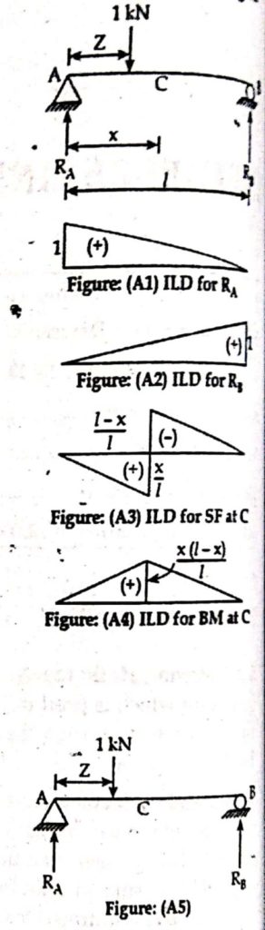
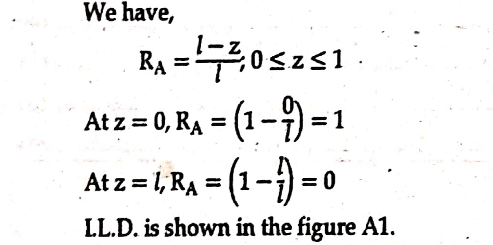
I.L.D for RA
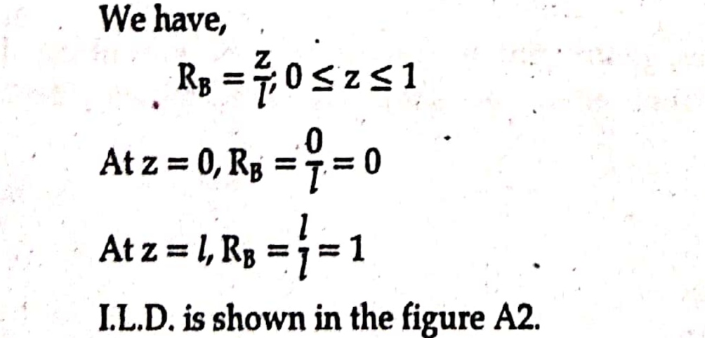
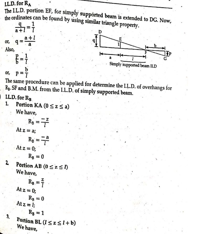
I.L.D for RB
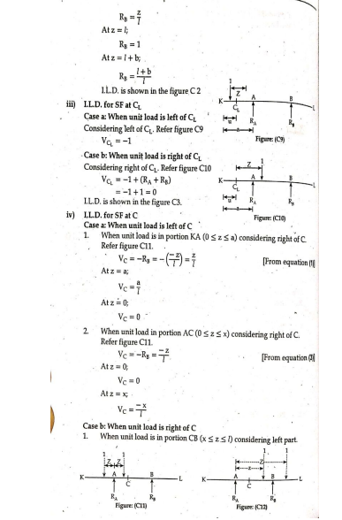
I.LD for shear force (S.F) at C
Case I : When unit load is in portion AC i.e. (0 ≤ z ≤ x)
Considering right of C ( as the number of loads are less in right portion)
SF at C, Vc = -RB = – z/L
Note: When rigid portion is considered upward force is taken negative.
Case II : When unit loads is in portion CB i.e. ( x ≤ z ≤ 1)
Considering left C.
VC=RA= 1-z/L
Note: Same result will be obtained by considering right of C.
- I.L.D for bending moment ( B.M.) at C
Case I : When unit load is in portion AC i.e.(0 ≤ z ≤ x)
Considering right of C.
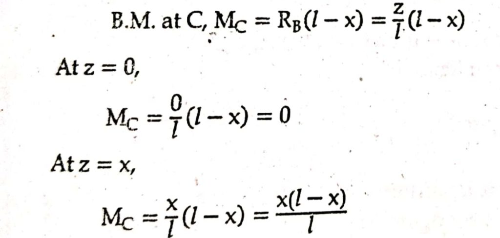
Case II : When unit load is in portion CB i.e ( x ≤ z ≤ L)
Considering left of C.

2. Cantilever beam
Consider a cantilever beam as shown below. Let unit load rolls from left to right.
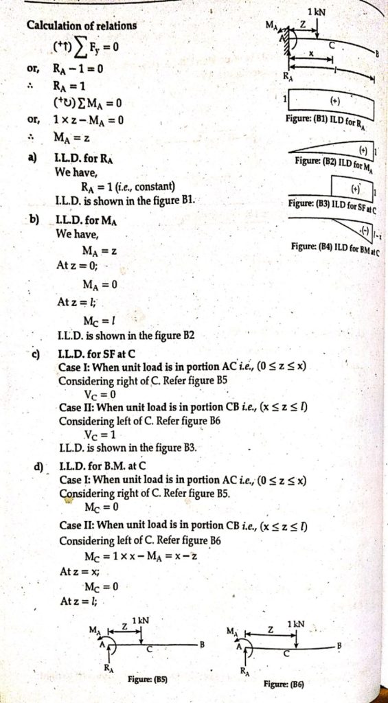
MC = x- L
I.L.D is shown in the figure B4
3. Overhanging beam
Consider an overhanging beam as shown below. The unit load rolls from left to right.
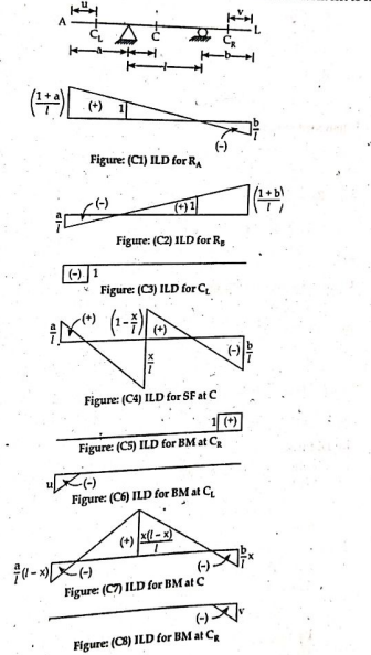
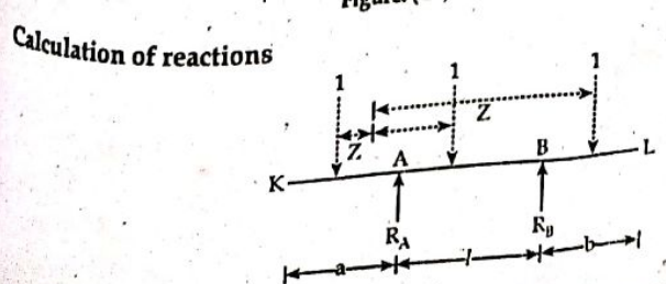

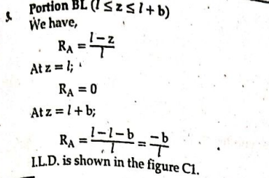
Note: The I.L.D for overhang portion can also be determined by extending the I.L.D of simply supported beam up to the overhangs and their ordinates is determined by using similar triangle property.


I.L.D for Truss
The I.L.D for truss members can be easily drawn using method of sections. We know from method of sections that the external forces acting on one side of section AA( either left side of right of section of the truss shown below) and the internal forces in the members U2U3 , U2L3 and L2L3 cut by the sections are in equilibrium.
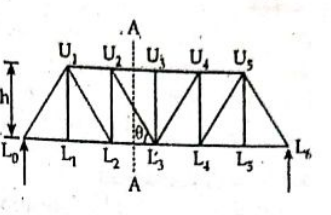
Applying principle of statics
For member L2L3
The moment of external forces about U2 acting either left or right side of section must be equal and opposite to the moment of the force in the bottom chord member L2L3 about U2.
(+↻)ΣMoment about U2 = 0
Let the moment of the external forces abour U2 be MU2
∴ Force in L2L3 = MU2 /h
For member U2U3
Similar, force in member U2U3 can be obtained by taking moment about L3 and applying:
(+↻)ΣMoment about L3 = 0
For member U2L3
Applying the sum of vertical component of all external forces on one side of section AA must be equal and opposite to the vertical component of the internal force in the member U2U3.
(+↑)Σ Fy = 0
Let the sum of vertical component of all external force is FV.
Force is U2L3 = Fy/ sinθ
- The moving loads are never carried directly on the main girder but are transmitted across cross girders to the joints of bottom chord.
- Bridge Truss Floor System
- A typical bridge floor system is shown in Figure. As shown in Figure, the loading on bridge deck is transferred to stringers. These stringers transfer the load to floor beams and then to the joints along the bottom chord of the truss.
- It should be noted that for any load position; the truss is always loaded at the joint.
Types of Trusses
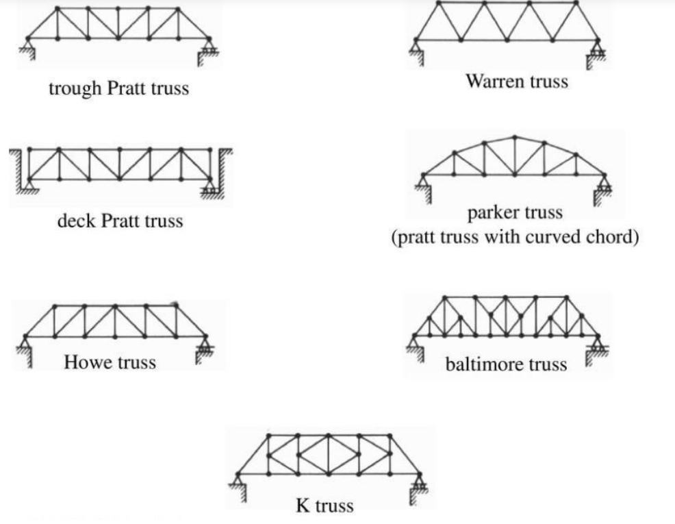
The main differences are that the Pratt truss has no force on the ends and the compression members are vertical. The Howe truss has no force on the center and the tension members are vertical instead.
Note :
- All top member compressive force and hence the I.L.D is negative.
- All the bottom experience tensile force and the I.L.D is positive.
- Vertical or inclined members experince tensile, compressive and both type of forces depending on the location with respect to the applied load on the truss.
I.L.D for Girders
Girder
Girder is a support beam which supports smaller beams. Girder is mainly used in bridges. In girder roof slab transmits the load to the cross beams and through cross beams to the girders. Hence, the girders are subjected to concentrated loads transmitted by cross beams.

The point at which the girder supports cross beam are referred as panel points.
1,2,3 and 4 are panel points.
The end reactions are not affected by the presence of cross beam. Hence, the reactions are same as that of simply supported beam.
The I.L.D for SF at any point within the panel is the same. Hence, I.L.D for SF is investigated with reference to panel but not any section.
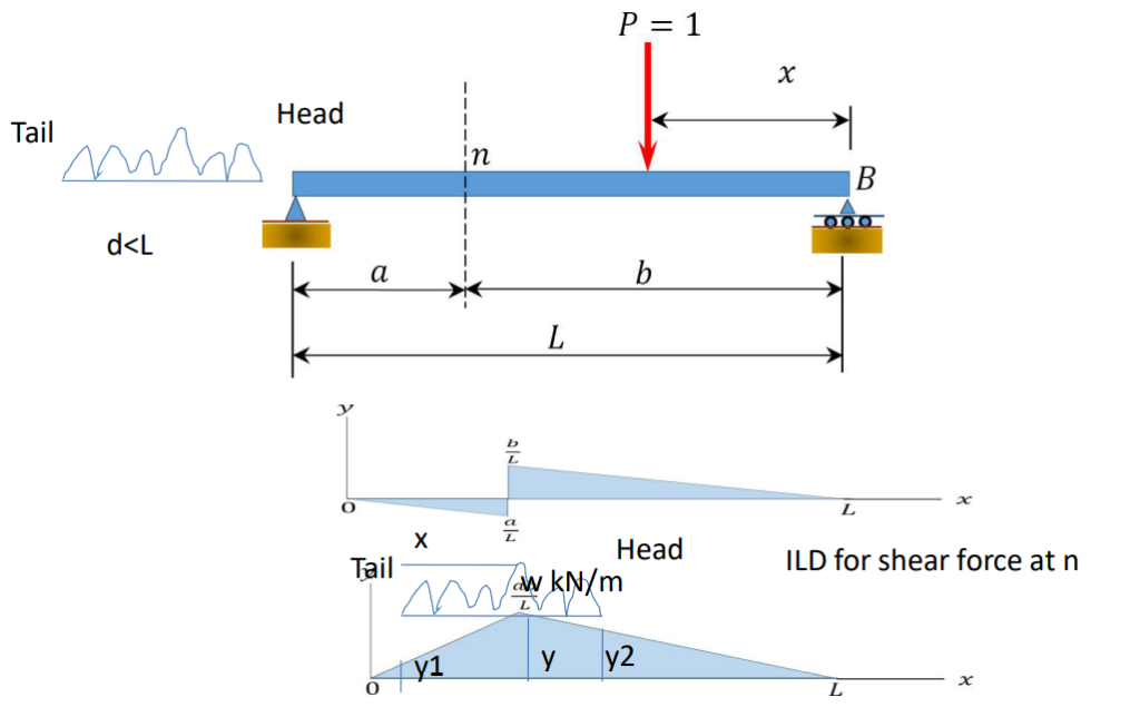
Beam subjected to U.D.L longer than span
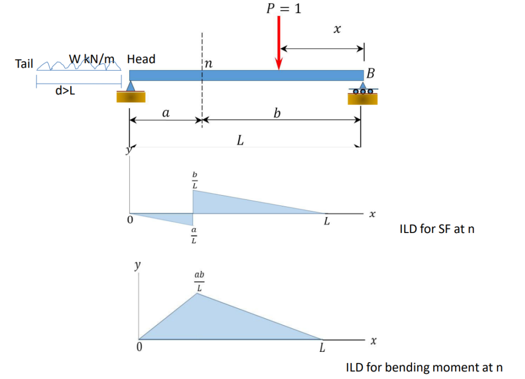
- Maximum negative shear force will be develop when head of udl reached considered section and absolute maximum negative shear force will developed when considered section is at B and the udl covers entire span.
- Maximum positive shear force will be develop when tail of udl reached considered section and absolute maximum positive shear force will developed when considered section is at A and the udl covers entire span.
- Maximum moment will be developed when the udl covers entire span and absolute maximum bending moment will developed when considered section is at mid span and load covers entire section.
Example:
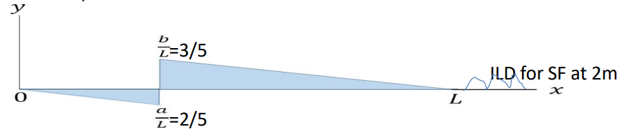
1. Draw Ild for shear force and bending moment at 3m from right support when 6m udl of intensity 4kN/m crosses over 5m simply supported bridge from left to right. Calculate maximum negative, maximum positive shear force, maximum moment and also calculate absolute maximum positive, negative shear force and bending moment.
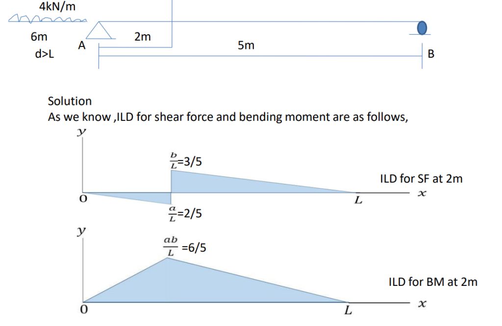
Maximum negative shear force will be develop when head of udl reached considered
section,

Maximum negative Shear Force = Intensity of load * Area under load in ILD
= 4(1/2)2*(2/5)
= 1.6 kN
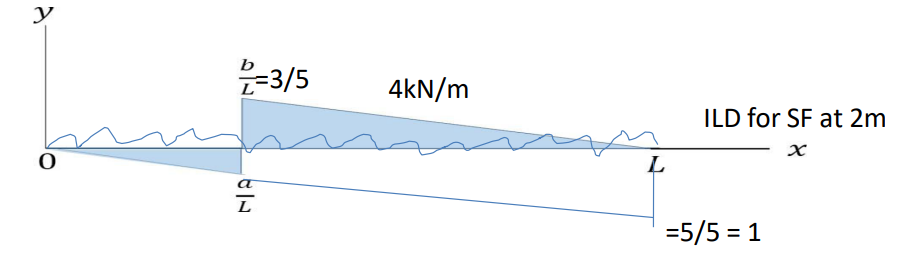
Maximum positive shear force will be develop when tail of udl reached considered
section ,
Maximum positive Shear Force = Intensity of load * Area under load in ILD
= 4(1/2)3*(3/5)
= 3.6 kN
Maximum moment will be developed when the udl covers entire span
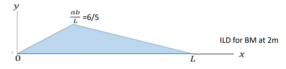
Maximum bending moment= Intensity of load * Area under load in ILD
= 4(1/2)5*(6/5)
= 12 kN m
Absolute maximum negative shear force will developed when considered section
is at B and the udl covers entire span.
Absolute Maximum negative shear force= Intensity of load * Area under load in ILD
= 4(1/2)5*1)
= 10 kN
Absolute maximum positive shear force will developed when considered section
is at A and the udl covers entire span.
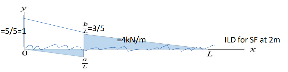
Absolute Maximum positive shear force= Intensity of load * Area under load in ILD
= 4(1/2)5*1)
= 10 kN
Absolute maximum bending moment will developed when considered
section is at mid span and load covers entire section.

Absolute Maximum moment= Intensity of load * Area under load in ILD
= 4(1/2)5*6.25/5)
= 12.5kN m
Beam subjected to U.D.L shorter than span
- Maximum negative shear force will be develop when head of udl reached considered section and absolute maximum negative shear force will developed when considered section is at B and the head of udl reached at B.
- Maximum positive shear force will be develop when tail of udl reached considered section and absolute maximum positive shear force will developed when considered section is at A and tail of udl reached at A .
- Maximum moment will be developed when the udl is so placed that the section divides the load in the same ratio as it divides the span i.e x/d=a/l and absolute maximum bending moment will developed when considered section is at mid span such that x/d=a/l is same. Where x= distance between considered section to tail of load,d=length of udl, a=distance from left support to considered section, l= span length
Example:
1. A simply supported beam has span of 15 m, udl of 40 kN/m and 5 m long crosses the girder from left to right. Draw ILD for shear force and bending moment at 6m from left support and calculate maximum shear force and bending at that section.

Maximum negative shear force will be develop when head of udl reached considered
section ,
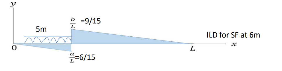
Maximum negative Shear Force = Intensity of load * Area under load in ILD
= 40(1/2)5*((1/15) +(6/15))
= 46.67 kN
Maximum positive shear force will be develop when tail of udl reached considered
section ,
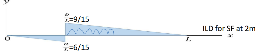
Maximum positive Shear Force = Intensity of load * Area under load in ILD
= 40(1/2)5*((9/15)+(4/15)
= 86.67 kN
Maximum moment will be developed when the tail of udl lies at x distance from
considered section towards left support. So x= 5*6/15 =2m

Maximum bending moment= Intensity of load * Area under load in ILD
=( 40(1/2)2((36/15)+(54/15)))+ ( 40(1/2)3((36/15)+(54/15)))
= 600kN m
I.L.D due to series of concentrated loads
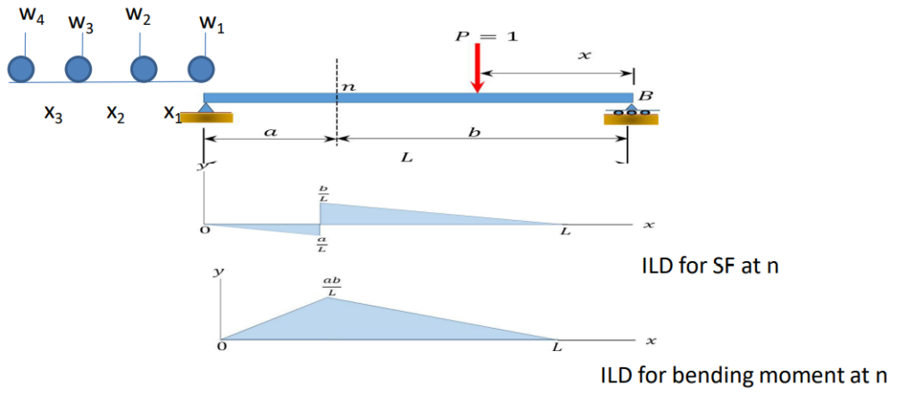
- Rolling loads are those loads which roll over the given structural element from one end to the another.
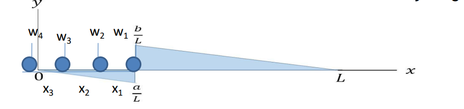
- For maximum negative shear force, most of the load lies in left portion of considered section so for that several hit and trial are made.
- Trial 1:Leading load w1 lies at considered section. Then,SF1 =w1*(a/L)+w2 *Y2 +w3 *Y3
- Trial 2 : W2 lies at considered section. Then SF2 =- w1*y1+w2*(a/l)+w3*y3+w4*y4
Check, If SF1>SF2,then maximum –ve shear force is SF1 otherwise next trial is made by placing W3 over considered section. In this way we made hit and trial inorder to get maximum –ve SF. For maximum positive shear force, most of the load lies in left portion of considered section so for that several hit and trial are made.
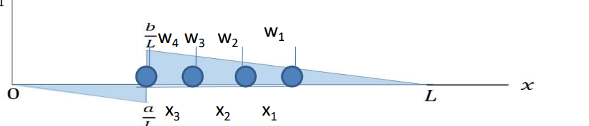
Trial 1:Following load w4 lies at considered section. Then,SF1 =w4*(b/L)+w3 *Y3 +w2 *Y2 + w1 *Y1
Trial 2 : W3 lies at considered section. Then SF2 =- w4*y4+w3*(b/l)+w2*y2+w1*y1

Check, If SF1>SF2 ,then maximum +ve shear force is SF1 otherwise next trial is made by placing W3 over considered section. In this way we made hit and trial inorder to get maximum –ve SF.
For maximum positive shear force, most of the load lies in left portion of considered
section so for that several hit and trial are made.
Trial 1:Following load w4
lies at considered section. Then,SF1 = w4 *(b/L)+ w3 * y3 + w2 * y2 +
w1 * y1
Trial 2 : w3 lies at considered section. Then SF2
=- w4 y4 + w3 (b/l)+w2y2+ w1 * y1
Check, If SF1 > SF2 ,then maximum +ve shear force is SF1 otherwise next trial is made by placingW3over considered section. In this way we made hit and trial in order to get maximum –ve SF.
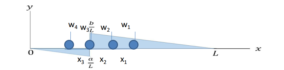
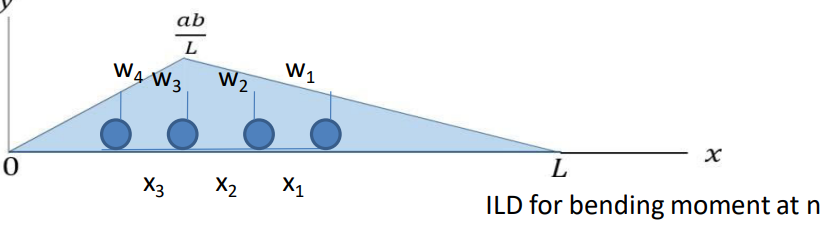
Maximum bending moment at a given section
- Maximum bending moment will be developed at a considered section when tilting load lies over that section.
- Tilting load: The load which changes the sign of avg. load on left side minus avg.load on right side when the point load passes over the section.
Tilting load can be determined as follows:

Here,w3 changes the sign so tilting load is w3 .Then tilting load is placed over considered section in order to get maximum moment.
Absolute maximum bending moment
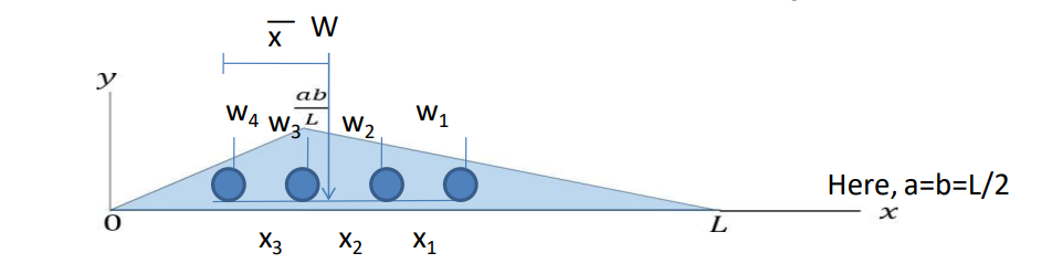
- When a train of several loads crosses a simply supported beam, the absolute maximum bending moment under any given wheel occurs when this wheel load and the c.g of total resultant load are equidistance from the centre of beam.
- Steps to find absolute maximum bending moment
- Calculate total resultant load by using,W= w1+w2+w3+w4
- Calculate the position of resultant load by taking moment about the position of following load, i.e W*x͞ = w4*0+w3*x3+w2*(x2+x3)+w1*(x1+x2+x3) Here, a=b=L/2 – Assume w3 is heavier and closer with resultant load W, so place w3 and resultant load W at equidistance from centre of beam.
- Calculate Bending moment by using concept of ILD uses.
- If w3 is heavier but farther with resultant load W, so we made hit and trial by placing w3 and resultant load W at equidistance from centre of beam for first case, and place w2 and resultant load W at equidistance from centre of beam for second case then compare two cases, and adopt the values which is greater.
References: 1. Theory of Structure I, Dr. Kamal Bahadur Thapa