
Design of sewer line means finding out the cross section of sewer and the slope at which it is to be laid to transport the estimated quantity of sewage. Unlike pressurized flow in water supply pipelines, top surface of sewage is in contact with atmosphere and the flow type is open channel flow.
Important considerations while designing sewer lines:
- Meeting self-cleaning velocity:
Sewage that flows in sewer has some solid particles on it (0.1%), in order to avoid clogging of these solid particles it is necessary that sewer pipe be so designed and laid at such gradient that it causes self-cleaning velocity at different possible discharges.
- Maintaining continuous gradient in the downward direction
Sewer conduits carry sewage as open channel and the source of energy is gravity. It is important that sewer be laid in downward direction up to the outfall point.
Hydraulic formula for sewer design
1. Manning’s formula
Most common formula used for calculation of velocity in open channel

Where, N= manning’s roughness coefficient
R=hydraulic mean depth=wetted area/wetted perimeter
S=bed slope of the sewer
For Cement concrete, (hume pipe) N=0.013
2. Chezys formula
Velocity calculated from chezy formula

Where,
R=hydraulic mean depth
S=bed slope of the sewer
For Cement concrete, ( hume pipe) N=0.013
C= Chezys roughness coefficient
C depends on the nature of surface, flow characteristics, shape and size of sewer, slope so it is complex. C is calculated from Kutters formula or Bazins formula.
3. Kutters formula for C calculation

Where,
R=hydraulic mean depth
S=bed slope of the sewer
N= rugosity coefficient, the value of which depends on the nature of inside surface of the sewer. For cement concrete pipe N may be taken as 0.013
4. Bazin’s formua for C calculation

Where,
R=hydraulic mean depth
K= Bazins constant, the value of K can be taken as 0.833 for cement concrete surface.
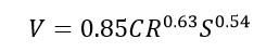
5. Hazens William formula
Velocity from hazens William formula is calculated as
Self-cleansing velocity, minimum velocity and maximum velocity
The flow velocities in the sewer should be such that neither it creates clogging of suspended materials nor it scours the pipe material due to excessive abrasion. This conditions set two limiting velocity.
Minimum velocity:
The problem of silting of solid particles in sewer can be prevented by setting velocity that can automatically create self-cleaning effect. It is important that this velocity is maintained in the sewer line at least once a day.
Maximum velocity or non-scouring velocity
Shield’s expression for self-cleaning velocity
Self-cleaning velocity can be determined as follows:
Consider a layer of sediment of unit length, unit width and of thickness t is deposited at the invert of a sewer of gradient Ө. Let γsub be the submerged unit weight of the sediment.
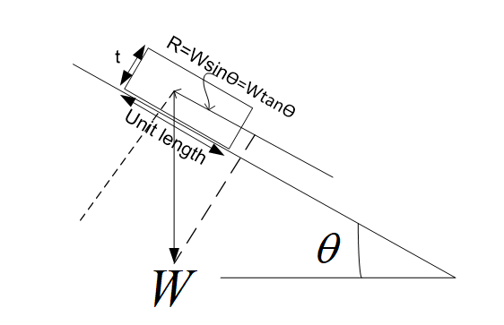
The weight of the sediment, W= γsub *(1*1)*t
But, γsub = γw * (Ss – 1) / (1+e)
Where
γw = unit weight of water
Ss = Specific gravity of the sediment
e= void ratio of the sediment
Relation of void ratio e and porosity of sediment n
Therefore,
(1 – n) = 1 / (1+e)
Therefore, γsub = γw * (Ss – 1) * (1- n)
W= γw * (Ss – 1) * (1- n) *t
In order to scour the deposited sediment and to cause it to slide down the inclined plane, it is necessary that the drag force Ʈ exerted by the flowing water on the surface of the channel equals the frictional resistance R
Ʈ=R
But R=WsinӨ=WtanӨ, for small Ө
Therefore, Ʈ= WsinӨ
Ʈ= γw * (Ss – 1) * (1- n) *t sinӨ
Drag force exerted by flowing water on the sediment is given by
Ʈ= γw * r * s
Where, r=hydraulic mean depth of the channel
s=bed slope of the channel
γw * (Ss – 1) * (1- n) *t sinӨ = γw * r * s
Considering, (1-n) sinӨ=k, k being a characteristics of sediment
s = k/r * (Ss – 1) t
Since t is volume per unit area, it can be considered as d for a unit grain of sediment
Therefore self-cleaning slope is given as
s ∝ k/r * (Ss – 1) d
This self-cleaning slope is replaced in chezy formula for getting self-cleaning velocity
V = C* (RS)1/2
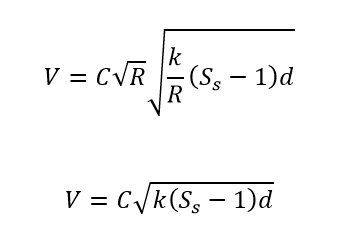
C can be replaced in the form of friction factor, by comparing chezys formula with Darcy weisbach formula
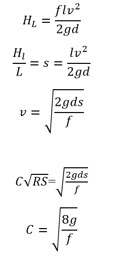
Self-cleaning velocity in the form of friction factor is
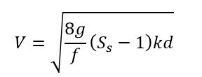
The usual value of friction factor for sewer is 0.03
Similarly, self-cleaning velocity using manning’s formula is
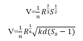
The usual value of for cement concrete pipe is 0.013
From the above expression, for inorganic particles of 1mm diameter a minimum velocity of 0.45m/sec is to be maintained likewise for removal of organic particle of 5mm diameter it is necessary to have velocity of 0.45m/sec for self-cleaning action. If it is required to cleanse inorganic particle greater than 1mm diameter and organic particle greater than 5mm diameter then the minimum velocity will be consequently higher.
The importance of maintaining minimum velocity is
- It helps in controlling the size of sewer
- It prevents silting of organic particles and inorganic particles. By flushing organic particles the problem of anaerobic decomposition in the sewer is controlled, which otherwise would create a problem of corrosion due to release of corroding gases such as hydrogen sulphide and methane. Likewise by flushing inorganic particles, problem of clogging and its effect is controlled.
Note: The larger the diameter of the sewer pipe, the gentler the slope is.
In practical cases, the gentlest slope that can be adopted is (1/diameter)
In flat terrain, where it is difficult to maintain minimum velocity on the beginning part of sewer network, it may be impossible to maintain self-cleaning velocity, in such case, flushing tanks are provided that helps to flush out the clogged sediments.
Maximum velocities:
It is observed that if the velocity of flow in sewer is very high then the smooth interior surface starts getting scoured due to continuous abrasion caused due to the high speed particles colliding on it. It thus becomes necessary to limit non scouring velocity.
For different types of sewer material non scouring limiting velocity (maximum velocity) is provided in the table below
| S.no | Sewer Material | Limiting velocity in m/sec |
| 1 | Vetrified tiles and glazed bricks | 4.5-5.5 |
| 2 | Cast iron sewers | 3.5-4.5 |
| 3 | Cement concrete sewers | 3 |
This problem frequently occurs in hilly terrain with steep slope. This problem is addressed by providing drop manholes at regular interval.
Shapes of sewer
The most common shape of sewer is circular. However there are also other shapes of sewer that can be constructed and used.
1. Non-circular shaped sewer section
a. Rectangular shaped sewer section
| These section of sewer were common in the past. The major benefits are its easy construction and optimum earthwork in excavation. These sections however are not so hydraulically efficient and now are being commonly used for covered storm water drains. |
b. Horshoe shaped sewer section

| These sewer are used for discharging large sewage. The main challenge in using this shape of sewer is difficulty in its construction. |
2. Circular shaped sewer section

| Circular shaped is the most hydraulically efficient section as for a given area it has the least perimeter and hence the highest hydraulic mean depth. The other benefit is the round interior which does not cause deposition of sediments on it. The major disadvantage is its use in combined system where it becomes difficult to maintain velocity in dry weather flow condition. |
Sewer material
Sewer carries sewage that contains all kind of solid particle in it such as ash, sand, organic impurities, acids, alkaline etc. Sewer material should be durable enough to provide service for its intended design period and it must be resistant against the detrimental effects of solid particles flowing in sewage. In addition to it sewer material also has to withstand forces acting on it. Sewer material should in general should have following attributes:
- Withstand internal pressure of sewage
- Withstand pressure of external load
- Bear temperature stress
- Bear flexural stresses
- Resistant to bear detrimental effects of solid particles flowing in it.
- Must have minimum weight so that it can be easily handled, transported and laid in position
- Must not easily corrode
- Must not easily scour
- Able to create watertight joints
- Impervious so that water does not seepage in to it.
Types of sewer material
1. Salt glazed stoneware or vertified clay
Made from clay and shales of special qualities, mixed with water and placed in pipe and pressed with pressure of 0.85N/mm2. Pipe are burned in clinker at 150 o C at beginning, 6000c to 7500c and then finally 12000 C. Small quantity of salt is added into it which vaporize at high temperature and form glaze.
Merits
- Resistance to corrosion
- Cheap, durable, easily laid and joined
- Withstand hydraulic pressure
Demerits
- Heavy , bulky difficult in handling and transportation
- Weak
2. Plain or reinforced cement concrete pipe
PCC are manufactured in small size up to 450mm diameter and for larger diameter pipe RCC pipe are constructed with circumferential reinforcement to carry internal or external stresses.
The RCC pipes are further categorized into NP2-light duty RCC, non pressure pipes used for drainage and irrigation, NP3-medium duty non pressure pipes, for carrying medium traffic and NP4 popes , heavy duty non pressure pipes.
Merits
- Strong enough to withstand internal and external pressure
- Easily manufactured
Demerits
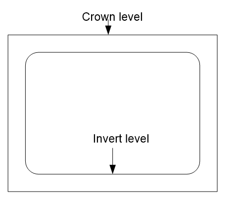
- Crown corrosion
- Heavy and brittle
3. Cast Iron Pipe
Cast iron pipe manufactured by sand molding method and the centrifugal process are structurally stronger and capable of withstanding tensile, compressive and bending stresses.
These pipes are costlier and hence used in special situation such as when sewage is to be pumped, when sewer is to be laid under the building and at insufficient depth below ground.
Advantages:
- High resistant to corrosion
- Withstand high internal pressure and external loads
- Strong and durable
Disadvantages
- Heavy and brittle
- Costly
4. Plastic sewer:
These are new types of pipes. Double wall corrugated pipes are recently being used as sewer. The major benefits of using these pipes are its light weight and easy transportation. Use of these pipe are still at its early phase.
Advantages
- Resistant to corrosion
- Economical
- Light weight, longer length so easy in handling and transportation
- Cheap and easily available
Disadvantages
- Affected by acidity and alkalinity
- Reduction in strength with increase in temp
- Easily cutoff
5. Asbestos cement pipe
These popes are manufactured from a mixture of asbestos fiber, silica and cement and converted under pressure to a dense homogenous material possessing considerable strength called asbestos cement.
Advantages
- Light in weight so easy to transport
- Easily cut and easily joined
- Resistant to corrosion
Disadvantages
- They are costly
- Unable to withstand pressure
- Brittle
6. Steel sewer
Sewer made up of steel material possesses high external and internal pressure bearing capacity. The major advantage of steel sewer is its light weight yet high flexibility and it can also absorb vibration and shock loads. It can be made corrosion resistant by galvanization or by bituminous coating. It can be easily coated. Despite having major benefits it is costly and used only on special cases.
Design of sewer network
- Calculation of maximum sanitary discharge Qs max for given sector from Upper Manhole(UMH) to lower Manhole(LMH) as per indexing of manholes & other related structures.
- Selection of Manning’s roughness coefficient (n).
- Calculation of ground slope of the section between UMH & LMH.
- Selection of internal diameter (D) of sewer pipe of circular crosses section & cross section in the case of rectangular reinforced conduit.
- Selection of slope (i) of sewer pipe in the given sector.
- Calculation of full discharge (Qfull) from nomograph based on Manning’s formula.
- Derivation of design depth of flow (h/D) from partial flow diagram (Q/Qfull).
- Derivation of actual velocity (Vactual) from partial (V/Vfull).
- Calculation of invert drops of manhole.
- Calculation of invert drops of sewer line.
- Calculation of invert elevation of upper manhole.
- Calculation of invert elevation of lower manhole.
- Calculation of depth of excavation down to invert level of UHM for the given sector.
- Calculation of depth of excavation down to invert level of LMH.
Sewer Design criteria
- Select the system of sewerage
- Determine the quantity of sewage
- Select the shape of sewer
- Select the sewer size range
- Sewer gradient (a site dependent factor, generally minimum gradient must meet self cleaning velocity and maximum gradient must meet non scouring velocity)
- Design depth, should not exceed 2/3 of diameter at full flow condition
Basic hydraulic formula
Discharge=Area*velocity
Velocity=manning’s or chezys formula
Hydraulic elements of sewer
Circular section running just full
Circular section running just full
A= π D2 / 4
P = πD
Hydraulic mean depth (R) =A/P=D/4
Circular section running half full
A= π D2 / 8
P = πD/2
Hydraulic mean depth R = D/4

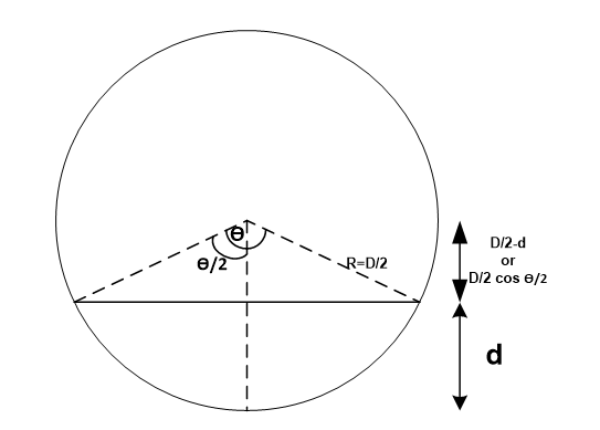
Circular section running partially full
Consider a sewer section of diameter D, d is the flow depth of sewage in sewer. let Ө be the central angle subtended in degrees at this flow depth.
For analysis we are considering following notation
| Full flow condition | Partial flow condition |
| Area=A | area=a |
| Perimeter=P | Perimeter=p |
| Velocity=V | Velocity=v |
| Hydraulic mean depth=R | Hydraulic mean depth=r |

a)Proportionate depth

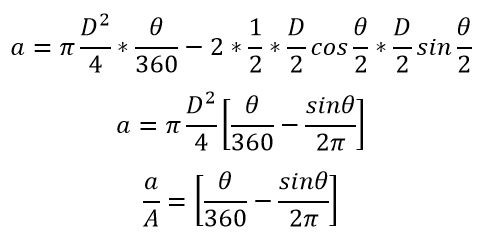
b) Proportional area
The area subtended by angle Ө
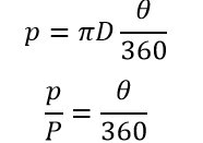
c) Proportional wetted perimeter
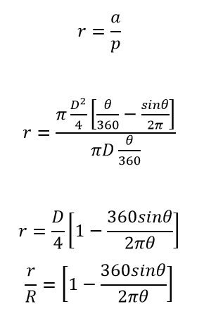
d) Proportional hydraulic mean depth
e) Proportional velocity of flow

f) Proportional discharge
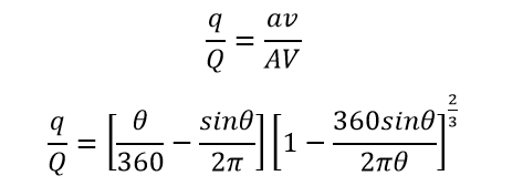
It is seen from the above expression that for different value of Ө, proportionate hydraulic elements can be calculated

It is important to note that the velocity and discharge in the partial flow sewer exceeds to that of full flowing sewer. For the case when N and n is considered to be same, maximum velocity occurs when depth is about 0.81 times the full depth. On other hand when N and n is considered different velocity is maximum in upper 20% depth only.
An important information can be derived from this result, sewers flowing between 50% to 80% depth need not be placed on steeper grades to be as self-cleansing as sewers running full.
Velocity and discharge are function of tractive force intensity which depends on the friction coefficient and the flow velocity. Ratios of vs/V, qs/Q and ss/S , where subscript s is denoting flow depth needed for maintaining self-cleansing velocity as that obtained in full flow condition can be computed with the help of equation on the assumption that equality of tractive force intensity implies equality of cleaning.
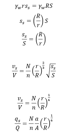
Eg: A 300mm diameter sewer is to flow at a 0.3 depth on a grade ensuring a degree of self-cleaning equivalent to that obtained at full depth at a velocity of 0.9m/sec. Find the required grade and associated velocity and rate of discharge at this depth. Assume Manning’s roughness coefficient n as 0.013. The variation of n with depth may be neglected.
Use of tables and nomograms for hydraulic computation for the design of sewers
While designing a sewer network, it becomes cumbersome to make calculation for computing the sizes and gradient of sewers required for developing requisite velocities at different discharge. To reduce this cumbersome task, readymade charts and tables, based on their original formulas are generally prepared, kept in design office and used.
For N=0.013, the unknown values say (Diameter and slope) can be find out for given two values (discharge and velocity).
300mm diameter sewer is to flow at a 0.3 depth on a grade ensuring a degree of self cleaning equivalent to that obtained at full depth at a velocity of 0.9m/sec. Find the required grade and associated velocity and rate of discharge at this depth. Assume Manning’s roughness coefficient n as 0.013. The variation of n with depth may be neglected.
Use
V=1/n R^2/3 S^1/2
R=A/P
d/D=0.3
Sewer is to be laid at such slope which will result in velocity of 0.9m/s as in full flow condition.
V=1/NR^2/3S^1/2
V=.9
N=0.013
R=D/4
S=.0043
r/R=.684
Vs=.846m/s
Q=AV=0.064 cumecs
q=av=0.015 cumecs
Figure Nomogram based on manning’s formula for sewer running full(N=0.013)
For different value of N , the parameter obtained must be multiplied by factor (0.013/N).
Stages of construction of sewer
1. Setting out of centerline of the sewer:
- Position of manholes are located on the ground from longitudinal section
- Sewer is laid from tail end or outfall end proceeding upward
- Sewer laid between two manholes at a time
- Center line is marked by
a. Offset method
- Central line of the sewer is marked on the ground .
- Offset line is marked parallel to the central line at suitable distance, about half the trench width plus 0.6m.
- line can be drawn by fixing the pegs at 15 m intervals.
b. Sight rail method
- Two vertical posts are driven into a ground at a known distance
- From center line peg and one horizontal rail (sight rail ) is fixed between these posts at some convenient height above ground.
2. Alignment and gradient
- Boning rods and sight rails are used to correct alignment and gradient
3. Excavation, timbering and dewatering of trenches
- Width of trench depends upon the external diameter of pipe.
- The depth of trench depends upon gradient
- Sewer line are below the GWT the ground water enters the trenches dewatering of trenches is done
Following precaution should be taken
- Timbering of trench should be done if the depth of trench is greater than 1.5m.
- In water logging areas continuous pumping to be done.
4. Laying and jointing of sewer
- Sewer pipes are lowered carefully by hanging on ropes
- Should be laid to the correct alignment and gradient
- Joining of pipes required to achieve required length
- Before jointing straightness is tested
- Types of joints depends upon sewer material
- Should be water tight
5. Testing of Sewer
a. Water Test:
- The sewers are tested after giving sufficient time for the joints to set for no leakage.
- sewer pipe sections are tested between the manholes to manhole under a test pressure of about1.5 m water head.
- the downstream end of the sewer is plugged and water is filled in the manhole at upper end.
- depth of water in manhole is maintained at about 1.5m.
- sewer line is inspected and the joints which leak are repaired.
b. Test for Straightness of alignment
- This can be tested by placing a mirror at one end of the sewer line and a lamp at the other end.
- If the pipe line is straight, full circle of light will be observed.
c. Air test:
- If no sufficient water and if the size of sewer is larger
- Subjecting pipe to an air pressure of 100mm of water by hand pump
- If pressure is maintained at 75mm of water , joint is assumed to airtight
d. Backfilling the trench:
- After the sewer line has been laid and tested, the trenches are backfilled.
- The earth should be laid equally on either side with layer of 15 cm thickness.
- Each layer should be properly watered and rammed.
Sewer appurtenances
These are structures constructed at suitable interval of sewer line that helps to connect sewer lines, allows bend in case of change in direction, joins branch sewer to main sewer, gives access for inspection for maintenance, facilitates hydraulic function, make the design economic and technically feasible.
Manhole
A manhole is a structure along a sewer line connecting sewers and providing an opening for access helping to inspect and maintain sewer performance. Manhole may be rectangular or conical section.
Location of manhole
Manhole is provided along the center line of sewer. It helps to connect laterals to the branch sewer and branch to the main sewer line. It is provided whenever there is change in direction of sewer line, change in diameter of sewer, change in gradient of sewer line.
Spacing of manhole
Spacing of manhole depends on the change in direction of sewer line, diameter of sewer pipes and change in gradient. However in general sense the spacing of manhole is close if the diameter of the pipe is small and it increases with diameter of pipe. If there is no obstruction, sewers of diameter less than 0.3m can be spaced in 45m whereas in the case of bigger size sewer, the spacing can be made up to 100m.
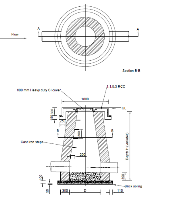
Components of manhole
- Top cover and frame
Every manhole is provided with top cover with frame as it is needed for covering access hole of the manhole. Depth of the frame is 20-25cm and width is 10cm whereas the opening should be at least 50cm.
- Access shaft
The upper portion of the manhole is called access shaft which provides an access to the working chamber. Its size is narrower than the bottom part. In rectangular manhole its size is 0.6m*.75m and for circular it is 0.6m diameter
- Working chamber
It is the lower portion of manhole which provides working space and have a minimum of 0.9m *1.2, size for rectangular and 1.2m diameter for circular shape.
- Bottom or invert or benching
The bottom is made up of concrete bed with slope towards center.
- Steps or ladder
Steel steps are provided for access to the bottom part of the manhole.
Manholes are of various types, one classification is done in the basis of its depth
- Shallow manhole: Manholes with depth ranging from 0.75m-0.9m . Generally occurs on the branch line.
- Normal or medium manhole: Manhole with depth ranging from 0.9m -1.5m.
- Deep Manhole: When the depth of the manhole exceeds 1.5m then it is called deep manhole.
Drop Manhole
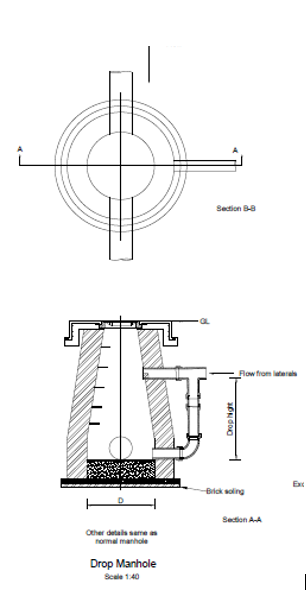
These are the type of manhole constructed when there is change in elevation of incoming sewer and the outgoing sewer. The drop should be made by means of an outside connection. Sometimes when a lateral sewer needs to be placed deep enough to meet the deeper main sewer line, use of a drop manhole allows the lateral to be maintained at a shallow slope thereby reducing the amount of excavation. The sewage drops into the lower sewer through the vertical pipe at the manhole.
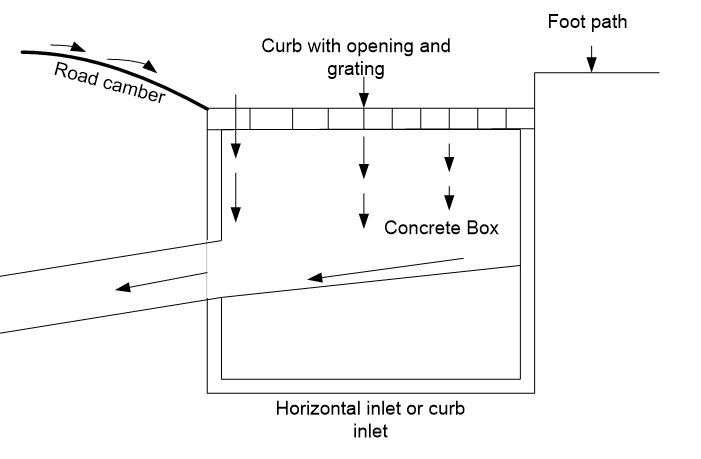
Street inlet
These are openings constructed at the road junctions and intersections for intercepting storm water and conveying it to the sewer line. The top part of the inlet is provided with MS grating cover that is durable enough to bear heavy traffic and pedestrian step.
Street inlets are further categorized as
- Curb inlet
It is also called as vertical inlet as it provides vertical opening for storm water to be accumulated in it.

- Gutter inlet
It is also called as horizontal inlet as it has horizontal opening on its top for the entrance of storm water
- Catch Basin or pits
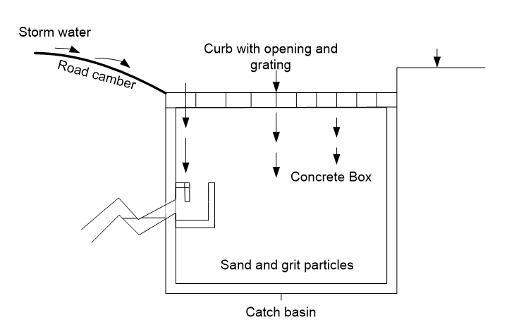
It is a special type of inlet which allows grit, sand and debris etc. flowing in the storm water settle out. The outlet is provided with a trap to prevent escape of odor from the sewer.
Flushing Tanks
These are the devices or tanks in connection with sewer line and placed at the location where it is difficult to maintain self-cleaning velocity of a sewer line. The water stored in these tanks are flushed which helps in cleansing of the sediment that silts due to insufficient self-cleaning velocity. Normally in flat terrain where it is difficult to maintain the velocity due to gentle slope these tanks are used. There are two types of flushing tanks a. Hand operated flushing tank and b. Automatic flushing tank.
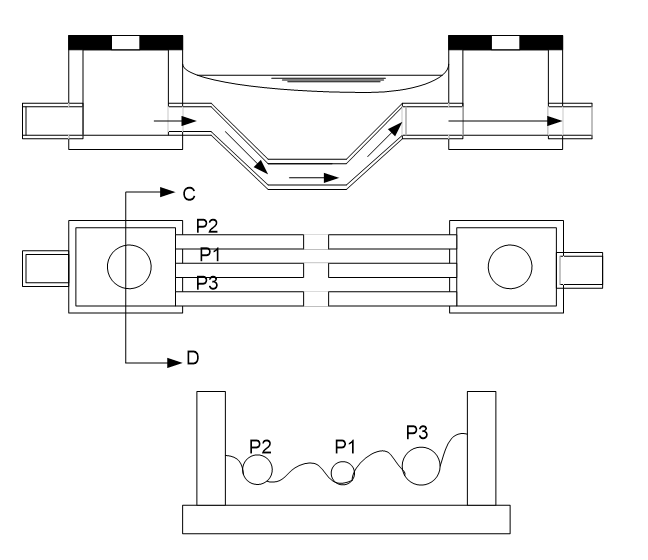
Inverted siphon
Inverted siphon is a depressed sewer laid at a gradient deeper than its HGL line. The need of this type of sewer is in situation when it is necessary to cross through road, railway tracks, canals etc lying on the level lower than sewer. In these sewer flow is in pressure greater than atmosphere. The arrangement consists of inlet and outlet chamber connected by three different sizes of pipes parallel to each other. The use of three pipe helps in meeting self cleaning velocity of 1m/sec in case of minimum flow. It is important to meet this self cleaning velocity at the minimum flow as cleaning of inverted sewer is extremely difficult. By providing lateral weirs when the flow is minimum only pipe 1 which is of smallest size will function and as the flow increases pipe 2 and pipe 3 subsequently comes into operation.
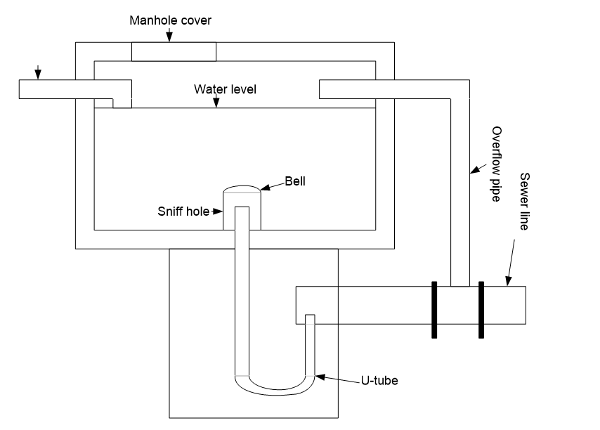
Ventilation in shaft
The decomposition of sewage release harmful and odorous gas. These gases are poisonous causing a threat to maintenance person and they are also corrosive which can reduce the life of the sewers. It thus becomes necessary to expel these gases through suitable opening. These opening are called ventilation which are provided at every 80m-300m. In open area ventilation is connected to the manhole cover but in crowded area air tight ventilating shaft with concrete base is used.

Sewer outlet
Outlets are the last structure of sewer from where treated waste water or storm water is discharged. If sewer is discharging to large water bodies of water it is usually extended beyond the banks into fairly deep water where dispersion and diffusion will aid in the mixing sewage with the surrounding water. In some cases outlets are anchored to prevent movement of the sewer line.
References:
- Modi, P.N. Environmental Engineering, Volume II : Waste Water Treatment, Disposal and Air Pollution Engineering. Delhi: Standard Book House.
- Garg. S.K. Environmental Engineering (Vol. II): Waste Water Engineering. Delhi: Khanna Publishers.