

1.1 Element of lateral load resisting masonry system
Elements of lateral load resisting masonry system are:
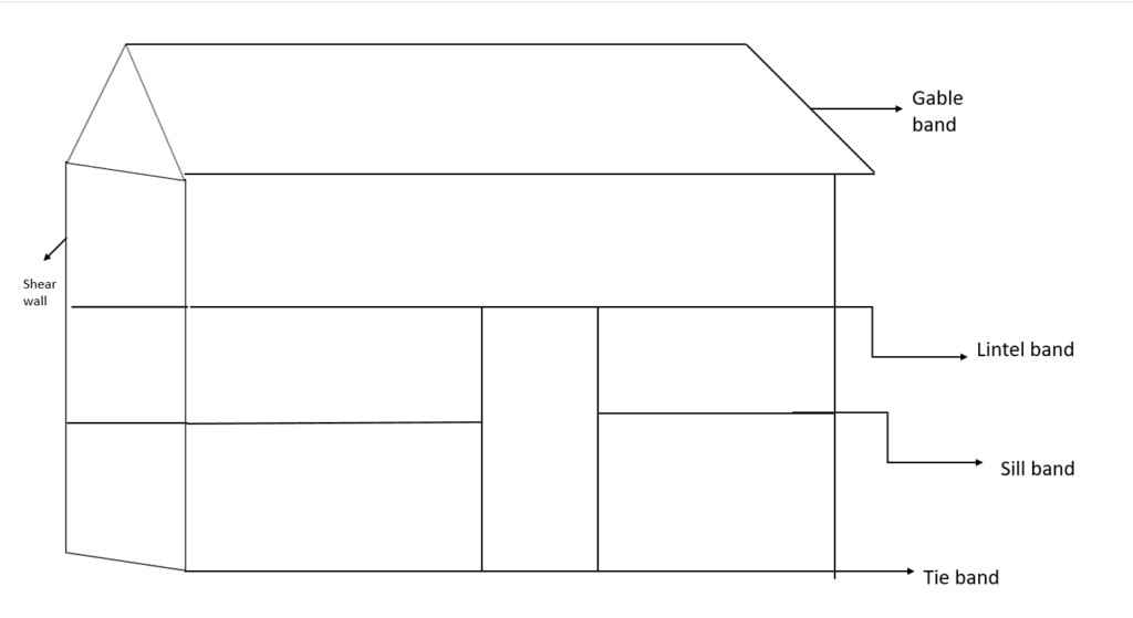
- Shear wall: A structural panel that can resist lateral force acting on it.
- Gable band: Building having slopped roof i.e. truss construction.
- Roof band: Used in building with roof made of flat timber or CGI sheet.
- Lintel band: Horizontal member placed at top of the opening like door and window to support unsupported wall above it.
- Sill band: Horizontal member placed at bottom of the opening to support load of opening frame.
- Tie beam: Horizontal beam that ties two structural member from separating.
1.2 In – plane and out of plane behavior of masonry wall
- Inplane and out of plane behavior of masonry wall are also called the failure mechanism of walls.
In – plane failure:
- Occurs when masonry element get pushed in the direction of the plane of wall.
Modes:
a. Sliding shear:
- Occurs when structure has low shear resistance than flexural strength.
b. Shear failure:
- An internal splitting force caused by two force acting in opposite direction.
c. Bending failure:
- Occur when tensile strength is equal or greater than ultimate strength of structure.
Out plane failure:
- Occurs when masonry element get pushed in the direction perpendicular to the wall.
Mode:
a. Topping failure:
- Forward rotation or movement of mass of structure due to vertical cracks.
b. Over turning failure:
- Occurs when movement equilibrium is not satisfied.
1.3 Failure behavior of masonry wall in lateral loads
- During lateral loading some portion of masonry walls undergo in tension and ultimately fails at tension zone.
- The failure modes depends upon the type of construction, amount and size of opening.
- The failure in unreinforced masonry building is due to structural defects such as lack of proper joint and large unsupported wall length.
The various failure in masonry structure:
- Diagonal shear cracks.
- Horizontal shear cracks.
- Bending cracks at lintels and feet.
- Bending cracks at corners.
- Bending crack at gable.
- Peeling of plaster.
1.4 Analysis for stresses on masonry wall under lateral loads
- When wall is subjected to lateral load such as wind, earthquake etc. bending will occur depending on support condition.
Consider a wall subjected to uniformly distributed vertical load P at centre line in one axis as shown in figure. The force is caused by self weight of wall, other external loading and applied uniform compressive stress across the section.
Compressive stress due to load P = P/A ———(i)
Again,
Consider lateral load ‘w’ KN/m2 applied to the section of wall and corresponding stress is given by
σb / y = M / I
or, σb = M*y / I
or, σb = M / Z [∴ I/y = Z]
where,
σb = Bending stress
M = Maximum bending moment
I = M.O.I about length of wall
Z = Section modulus
y = Distance of considered layer from NA
1.5 Ductile behavior of reinforced and unreinforced masonry structure
- Capacity of an element of structure to undergo large deformation without failure.
- Masonry is brittle in nature.
- Unreinforced masonry cannot withstand tension so cracks develops.
- Inplane and out plane failure is also due to ductility of masonry.
- To improve ductility reinforcing bars are embedded in the masonry to resist seismic force.
1.6 Compressive strength of masonry unit and masonry walls
Compressive strength of masonry units:
Apparatus required: Universal testing machine
Specimen: At least three number of masonry unit
Procedure:
- Place the specimen in flat face between the plates of testing machine.
- Applying axial load at a uniform rate of 140 kg/cm2 per minute till failure occurs.
- Maximum failure is noted.
σc = Maximum load of failure/ Average contact area
Compressive strength of masonry walls:
Apparatus required: Universal testing machine
Specimen: At least three number of brick with certain bond type
Procedure:
- Place the specimen in flat face between the plates of testing machine.
- Applying axial load at a uniform rate of 140 kg/cm2 per minute till failure occurs.
- Maximum failure is noted.
σc = Maximum load of failure/ Average contact area
1.7 Diagonal shear test
- In load bearing masonry wall shear wall carry vertical load and resist lateral load when combined loading creates tensile stress the tensile strength of masonry is exceeded leading tensile cracking.
- To evaluate masonry shear strength and shear elastic modulus diagonal test is performed on rectangular masonry specimen.
- In diagonal shear test a 1.2 * 1.2 m square section of wall is placed between the compressor to determine shear strength and shear modulus.
- Diagonal shear stress can be calculated by
τ = P / A * 21/2
where,
P = Applied load
A = Average cross section area of specimen
1.8 Non – destructive test
1. Elastic wave tomography:
- Used for locating shallow cracks and voids.
- Based on the principle of heat transfer i.e. conduction and radiation.
- Allows rapid mapping of internal condition.
- Material with no voids, gaps or cracks are more thermally conductive than material with moisture content.
2. Flat – jack test:
- Used to analyze and evaluate existing masonry structure.
- Uses small thin hydraulic jack to apply a force to a section of an existing masonry wall and measuring device determine the resulting displacement of masonry.
- Measure shear strength of structure.
- Measure compressive strength.
Types of flat jack test:
a. Single flat test or insitu shear test
b. Double flat jack test or insitu deformability test
3. Push shear test:
- Firstly, the brick, mortar are removed from test location. Also joint on opposite side also removed.
- Mortar joint above and below are not disturbed.
- Now, hydraulic ram is inserted along with pressure gauge to measure actual strength.
- A block is placed in order to distribute load uniformly and loading is done till cracking or movement is observed.
- Force at cracking or movement is noted to develop force deflection plot.
References:
- Dayaratnam, P. Brick and reinforced brick structure.
- Neville, A.M. Properties of Concrete. England: Pearson Education Limited.
- Hendry, A.W., Sinha, B.P. & Davies, S.R. Design of Masonry Structure. London: E & FN Spon.