
Introduction, intensity of pressure
Fluid Pressure at a point
Source:http://wwwmdp.eng.cam.ac.uk/web/library/enginfo/aerothermal_dvd_only/aero/fprops/statics/node4.html
Consider a small area dA in large mass of fluid. If the fluid is stationary, then the force exerted by the surrounding then the force exerted by the surrounding fluid on the area dA will always be perpendicular to the surface dA. Let, dF is the force acting on the area dA in the normal direction. Then the ratio of dF/dA is known as the intensity of pressure or simply pressure and this ratio is represented by P.
Mathematically,
Pressure at a point in a fluid at rest (P) = dF/dA
If the force (F) is uniformly distributed over the area (A),
Then,
Pressure (P) = Force (F)/Area (A)
Also,
Force or Pressure force (F) = Pressure (P) * Area (A)
Units of pressure are:
- kgf/m2 and kgf/cm2 in MKS units.
- N/m2 and N/mm2 in SI units.
Note: KPa = Kilo Pascal = 1000 N/ m2
Bar = 100 KPa = N/ m2
Pascal’s Law
Pascal law states that “the pressure or pressure intensity at a point in a static fluid is all direction.”
Intensity of pressure at a point in a fluid at rest is same in all direction:
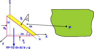
The fluid element is of very small dimensions i.e. dx, dy, and ds.
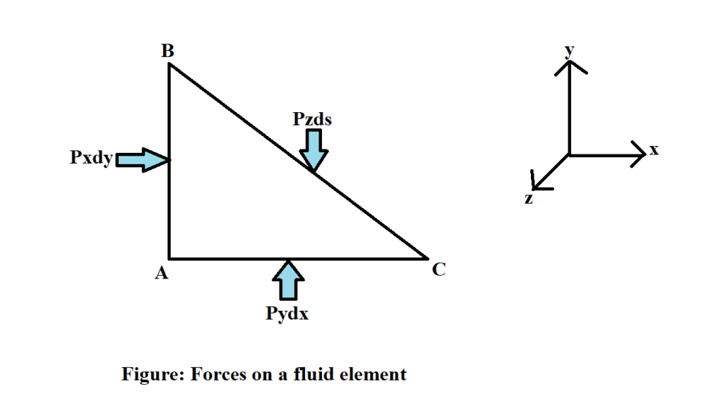
Consider an arbitrary fluid element of wedge shape in a fluid mass at rest as shown in figure. Let, the width of the element perpendicular to the plane of the paper is unity and Px, Py and Pz are the pressure or intensity of pressure acting on the force AB, AC and BC respectively.
Then,
Force on side AB = Px* Area of face AB
Or, Force on side AB = Px*dy*1
Or, Force on side AB = Px dy
Similarly,
Force on side AC = Py dx
Force on side BC = Pz ds
Weight (W) = Area of triangular element*depth*Specific weight
Or, W = 1/2* AB * AC *1*
Or, W = * dxdy * ρg
Resolving the forces in x-direction
Px dy = Pz ds sin (90- θ)
Or, Px dy = Pz ds cos θ
Also from figure,
dy = ds cos θ
Now,
Pxdy = Pz dy
Or, Px = Pz …………………. (i)
Similarly,
Resolving the forces in y-direction
Pydx = Pzds cos(90- θ) + 1/2* dxdy * ρg
Also,
dscos θ = dx {also the element is very small and hence weight is negligible}
Now,
Pydx = Pzdx
Or, Py = Pz ……………….. (ii)
From equation (i) and (ii), we have
Px = Py = Pz
The above equation shows that pressure at any point in x, y and z direction is equal.
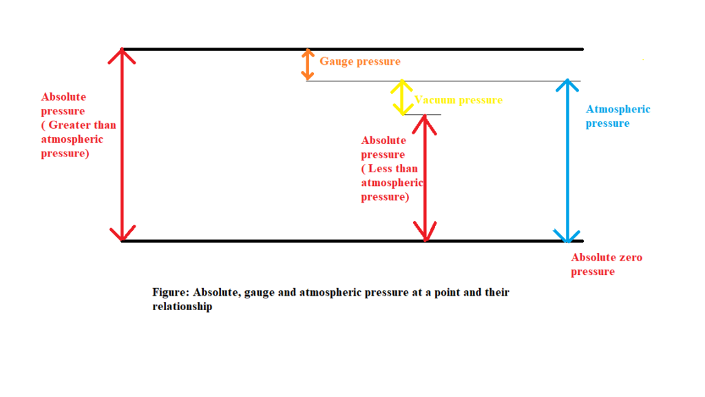
Absolute, gauge and atmospheric pressure at a point and their relationship:
Absolute pressure
Absolute pressure is a pressure that is relative to the zero pressure in the empty, air-free space of universe. This reference pressure is the ideal or absolute vacuum. Also, it is the sum of gauge pressure and atmospheric pressure.
i.e. Pab= Pgauge+Patm
Where,
Absolute pressure = Pab
Gauge pressure = Pgauge
Atmospheric pressure = Patm
Gauge pressure
Gauge pressure is defined as the difference between an absolute pressure and atmospheric pressure.
i.e. Pgauge = Pab – Patm
Where,
Absolute pressure = Pab
Gauge pressure = Pgauge
Atmospheric pressure = Patm
Atmospheric pressure
Atmospheric pressure is also known as barometric pressure, it is the pressure within the atmospheric of earth.
i.e. Patm= Pab – Pgauge
Where,
Absolute pressure = Pab
Gauge pressure = Pgauge
Atmospheric pressure = Patm
Vacuum pressure
A pressure reading below the atmospheric pressure is known as a vacuum pressure.
The graphical representation of relationship between Absolute, gauge and atmospheric pressure at a point:
Measurement of pressure
The pressure of a fluid is measured by the following devices:
Manometer :
Manometer are defined as the device used for measuring the pressure at a point in a fluid by balancing the column of fluid by the same or another column of fluid. They are classified as:
- Single manometers
- Differential manometers
2. Mechanical Gauges:
Mechanical gauges are defined as the device used for measuring the pressure by balancing the fluid column by the spring or dead weight.
The commonly used mechanical pressure gauges are:
- Diaphragm pressure gauge
- Bourdon tube pressure gauge
- Dead weight pressure gauge and
- Bellows pressure gauge
Manometer:
Simple manometer
A simple manometer consists of a glass tube having one of its ends connected to a point where pressure is to be measured and other end remain open to atmosphere.
The types of simple manometers are:
- Piezometer
- U- tube manometer and
- Single column manometer
- Piezometer

Piezometer is the simplest form of manometer used for measuring gauge pressures. One end of this manometer is connected to the point where pressure is to be measured and other end is open to the atmosphere as shown in figure. The rise of liquid gives the pressure head at the point. If at a point A, the height of liquid let water is “h” in piezometer tube, then Pressure at A = ρgh
Its SI unit is N/m2 .
2. U-tube manometer
U- tube manometer consist of glass tube bent in U- shape , one end of which is connected to a point at which pressure is to measured and other end remains open to the atmosphere. The tube generally contains mercury or any other liquid whose specific gravity is greater than the specific gravity of the liquid whose pressure is to be measured.
The types of U-tube manometer are:
- For Gauge Pressure
- For Vacuum Pressure
A. For Gauge pressure
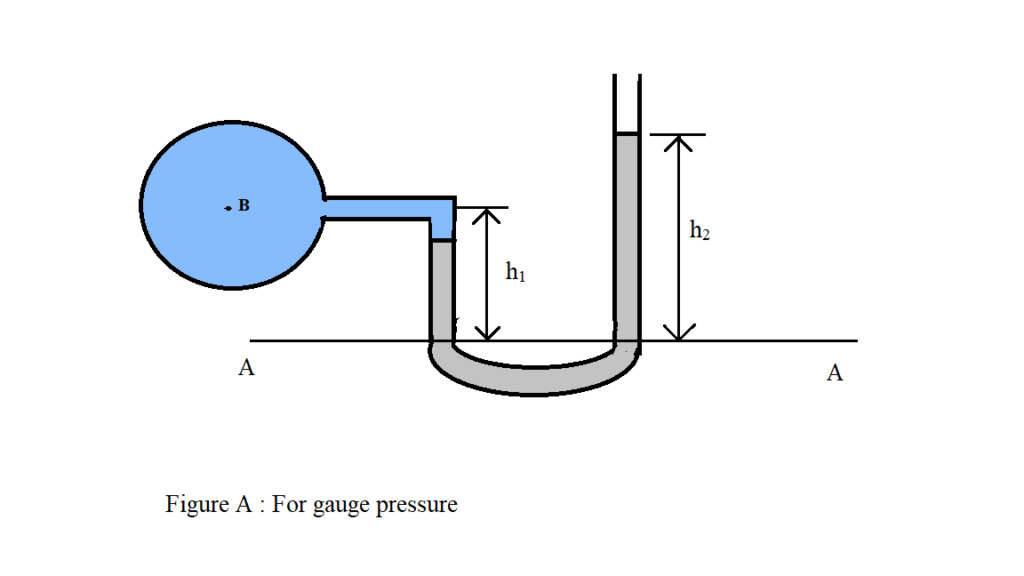
Let, B is the point at which pressure is to be measured, whose value is P. The datum line is A-A.
Let,
h1= Height of light liquid above the datum line.
h2= Height of heavy liquid above the datum line.
s1= Specific gravity of light liquid.
s2= Specific gravity of heavy liquid.
ρ1 = Density of light liquid. = 1000 * s1
ρ2 = Density of heavy liquid. = 1000 * s2
As the pressure is the same for horizontal surface. Hence, pressure above the horizontal datum line A-A in the left column and in right column of U-tube manometer should be same.
Pressure above A-A in the left column = P + ρ1 g h1
Pressure above A-A in the right columns = ρ2 g h2
Hence, equating the two pressure
P + ρ1 g h1= ρ2 g h2
Or, P = ρ2 g h2 – ρ1 g h1
B. For Vacuum pressure
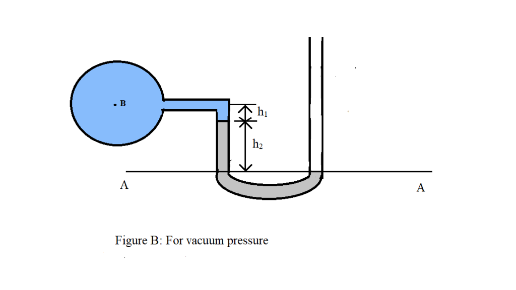
For measuring vacuum pressure the level of the heavy liquid in the manometer will be as shown in figure.
Let,
h1= Height of light liquid above the datum line.
h2= Height of heavy liquid above the datum line.
s1= Specific gravity of light liquid.
s2= Specific gravity of heavy liquid.
ρ1 = Density of light liquid. = 1000 * s1
ρ2= Density of heavy liquid. = 1000 * s2
Then,
Pressure above A-A in the left column = P + ρ1 g h1+ ρ2 g h2
Pressure above A-A in the right columns = 0
Hence, equating the two pressure
P + ρ1 g h1 + ρ2 g h2= 0
Or, P = – (ρ1 g h1 + ρ2 g h2)
3. Single column manometer
Single column manometer is a modified form of a U-tube manometer in which a reservoir having a large cross-sectional area (about 100 times) as compared to the area of the tube is connected to one of the limbs of the manometer. Due to large cross- sectional area of the reservoir for any variation in pressure the change in the liquid level in the reservoir will be very small which may be neglected and hence the pressure is given by the height of liquid in the other limb. The other limb may be vertical or inclined. Thus, there are two types of single column manometer as:
- Vertical single column manometer
- Inclined single column manometer
A. Vertical single column manometer

Above figure shows the vertical single column manometer. Let X-X be the datum line in the reservoir and in the right limb of manometer when it is not connected to the pipe due to high pressure at A, the heavy liquid in the reservoir will be pushed downward and will rise in the right limb
Let,
h1= Height of light liquid above the datum line.
h2=Height of heavy liquid above the datum line.
s1= Specific gravity of light liquid.
s2= Specific gravity of heavy liquid.
ρ1= Density of light liquid.
ρ2= Density of heavy liquid.
△h= Fall of heavy liquid.
P = Pressure at A.
A= Cross- sectional area of the reservoir.
a = Cross-sectional area of the right limb.
Fall of heavy liquid in reservoir will cause a rise of heavy liquid level in the right limb
A*△h = a * h2
Or, △h = (a * h2) / A (a)
Now, consider the datum line Y-Y as shown in figure.
Then,
Pressure in the right limb above Y-Y = ρ2g (△h + h2) (b)
Pressure in the left limb above Y-Y = ρ1g (△h + h1) + P (c)
Equating equation (b) and (c) , we have
ρ2g (△h + h2) = ρ1g (△h + h1) + P
Or, P = ρ2g (△h + h2) – ρ1g (△h + h1)
Or, P = △h [ρ2g – ρ1g] + h2 ρ2g – h1 ρ1g
From equation (a)
P = [(a * h2) / A ] * [ρ2g – ρ1g] + h2 ρ2g – h1 ρ1g
As, the area A is very large compared to a, hence ratio a/A becomes very small and can be neglected.
Thus,
P= h2 ρ2g – h1 ρ1g
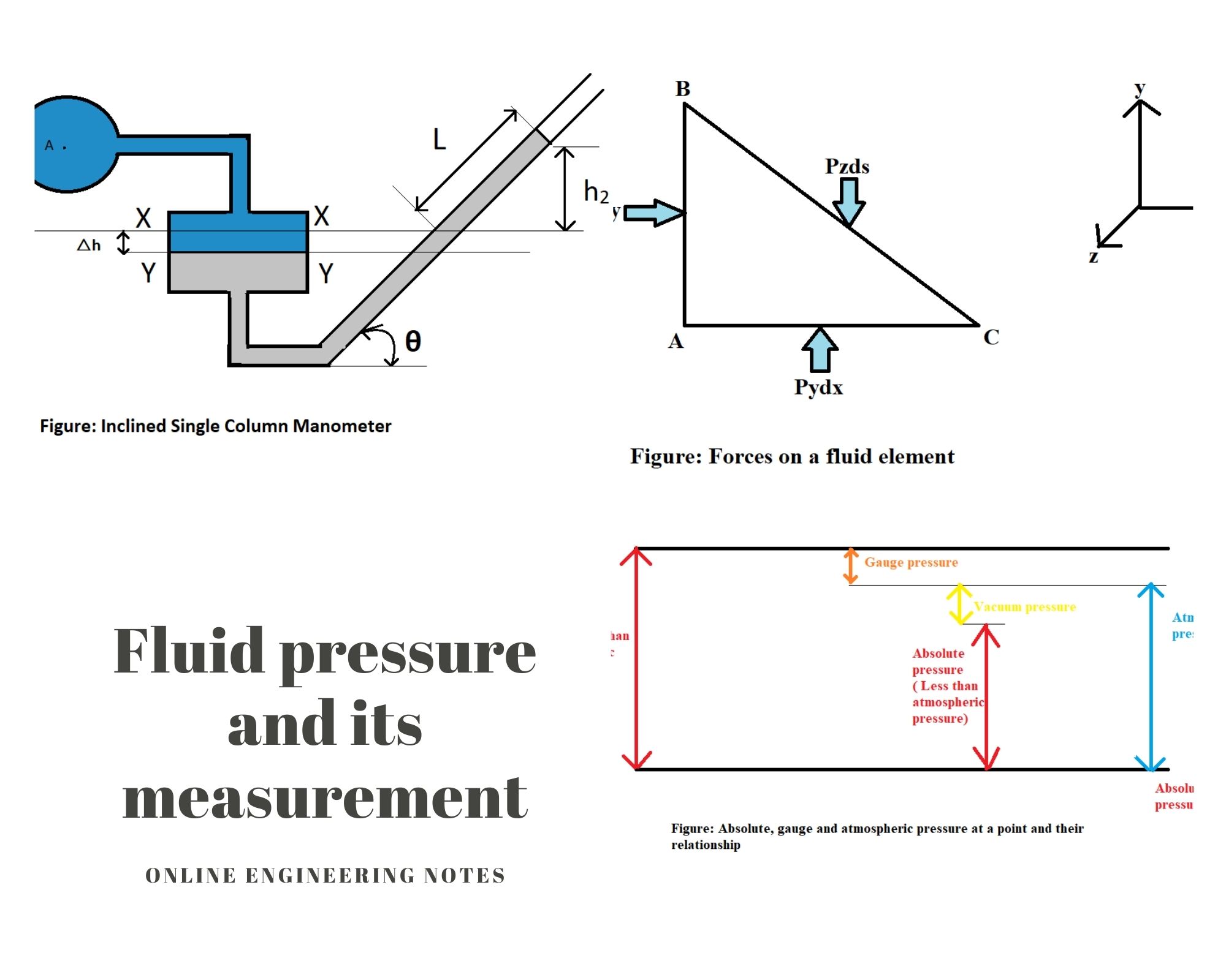
B. Inclined single column manometer

Above figure shows the inclined single column manometer. This manometer is more sensitive. Due to inclination the distance moved by the heavy liquid in the right limb will be more.
Let,
L= length of heavy liquid moved in right limb from X-X
θ = Inclination of right limb with horizontal
h2 = Vertical rise of heavy liquid in right limb from X-X
h2 = Lsinθ
Now,
From equation of pressure at A
P= h2 ρ2g – h1 ρ1g
Substituting the value of , we get
P=Lsinθ ρ2g – h1 ρ1g
Differential manometer
Differential manometer are the devices used for measuring the difference of pressure between two points in a pipe or in two different pipe. A differential manometer consists of a U- tube, containing a heavy liquid whose two ends are connected to the points whose difference of pressure is to be measured. Most commonly types of differential manometer are:
- U- tube differential manometer
- Inverted U-tube differential manometer
- U- tube differential manometer
Most commonly types of U- tube differential manometer are:
- Two pipes at different levels
- Two pipes are at same level
- Two pipes at different levels
In above figure the two points A and B are at different level and also contain liquids of different specific gravity. These points are connected to the U- tube differential manometer. Assume the pressure at A and B are
PA and PB respectively.
Let,
h= Difference of mercury level in U-tube
y = Distance of the center of B from the mercury level in the right limb
x= Distance of the center of A from the mercury level in the right limb
ρ1= Density of liquid at A
ρ2= Density of liquid at B
ρm= Density of heavy liquid or mercury
Pressure above X-X in the left limb = ρ1g(h+x) + PA
Pressure above X-X in the right limb = ρm gh + ρ2gy + PB
Equating the two pressure, we have
ρ1g(h+x) + PA = ρm gh + ρ2gy + PB
Or, PA – PB = ρm gh + ρ2gy – ρ1g(h+x
Or, PA – PB = hg(ρm – ρ1 )+ ρ2 gy – ρ1gx
- Two pipe are at same level
2. Inverted U-tube differential manometer
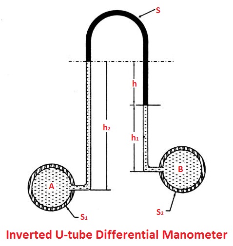
It consists of an inverted U-tube containing a light liquid. The two ends of the tube are connected to the points whose difference of pressure is to be measured. It is used for measuring difference of low pressure.
In above figure shown an inverted U- tube differential manometer connected to the two points A and B. Let, the pressure at A is more than the pressure at B.
Let,
h1= Height of liquid in left limb below the datum line X-X
h2= Height of liquid in right limb below the datum line X-X
h = Difference of light liquid
ρ1= Density of liquid at A
ρ2= Density of liquid at B
ρL= Density of light liquid
PA= Pressure at A
PB= Pressure at B
Then,
Pressure in the left limb below X-X = PA – ρ1 g h1
Pressure in the left right limb below X-X = PB – ρ2 g h2 – ρL gh
Equating the two pressure
PA – ρ1 g h1= PB – ρ2 g h2 – ρL gh
Or, PA – PB = ρ1 g h1– ρ2 g h2 – ρL gh
References: 1. A text book of fluid mechanics and hydraulic machines, Dr. RK Bansal, (2008), Laxmi publication(P) LTD.