

1.1 Components of surface gravity irrigation system:
1. Head work:
- Consist of all the works to store, divert and control river water and regulate supplies into canal.
2. Canal network:
a. Main canal:
- Large capacity canal which supplies water to branch canals and the major distributaries.
b. Branch canal:
- Supply water to major and minor distributaries.
c. Major distributaries:
- Use for direct irrigation.
- Supply water to minor distributaries.
d. Minor distributaries:
- Discharge is less than 0.25 cumec.
- Supply water through outlet to water course for irrigation.
e. Water course:
- Small channel managed by farmers to take water from minor to the field.
3. Structure in canal:
a. Cross drainage structure:
- Structure constructed at the crossing of canal and natural drainage.
- Use to disposal of drainage water without interrupting the continuous canal supply.
b. Canal fall:
- Use to carry canal water below stream or drainage.
c. Cross regulator:
- Constructed across a canal to regulate the water level in canal.
d. Canal escape:
- Constructed to escape extra water from the canal into natural drain.
1.2 Classification of canal:
A. Based on their function:
1. Irrigation canal:
- Canal used to fulfill irrigation water requirement.
2. Navigation canal:
- Canal used for transportation through water.
3. Hydropower canal / power canal:
- Canal use to supply water to power house to generate electricity.
4. Feeder canal:
- Canal that supplies water to two or more canals.
5. Link canal:
- Canal that link one river with the other.
B. Based on carrying capacity:
- Main canal
- Branch canal
- Major distributary
- Minor distributary
- Water course
C. Based on alignment:
- Watershed or ridge canal
- Contour canal
- Side slope canal
D. Based on financial output:
1. Protective canal:
- To protect particular area from famine.
2. Productive canal:
- To generate revenue to the nation.
E. Based on canal surface:
1. Lined canal:
- Canal with their surface lined by impervious material like concrete, brick etc.
2. Unlined canal:
- Canal with their surface in natural condition.
F. Based on nature of source:
1. Permanent canal:
- Canal that have continuous supply from the source like lake or perennial river or ice.
2. Inundation canal:
- Canal in which flows occurs only during the high stage of river.
1.3 Components of canal cross- section:

1. Side slope:
- Used for stable canal.
- Depends upon type of soil.
- Steeper slope is provided in cutting.
2. Berm:
- Used for deposition of silt which acts as a lining.
- Reduce seepage.
- Protect bank from erosion.
3. Free- board:
- Margin between full supply level (FSL) and bank level.
- Depends upon size of canal:
| Discharge in cumec | Extent of FBL |
| 1 to 5 | 0.5 |
| 5 to 10 | 0.6 |
| 10 to 30 | 0.75 |
| 30 to 50 | 0.9 |
4. Canal banks:
- Primary purpose is to retain water.
- Used for inspection and as means of communication.
5. Service road:
- Roads provided on canal for inspection purpose.
- Provided 0.4 m to 1 m above FSL (Full supply level) depending upon canal size.
6. Spoil bank:
- Constructed when earth work in excavation exceed earthwork in filling.
- Disposal of such soil may be uneconomical by mechanical means.
1.4 Alignment canal:
1. Watershed or ridge canal:

- Line separating the catchment of two streams is ridge line.
- No drainage can intersect watershed.
2. Contour canal:
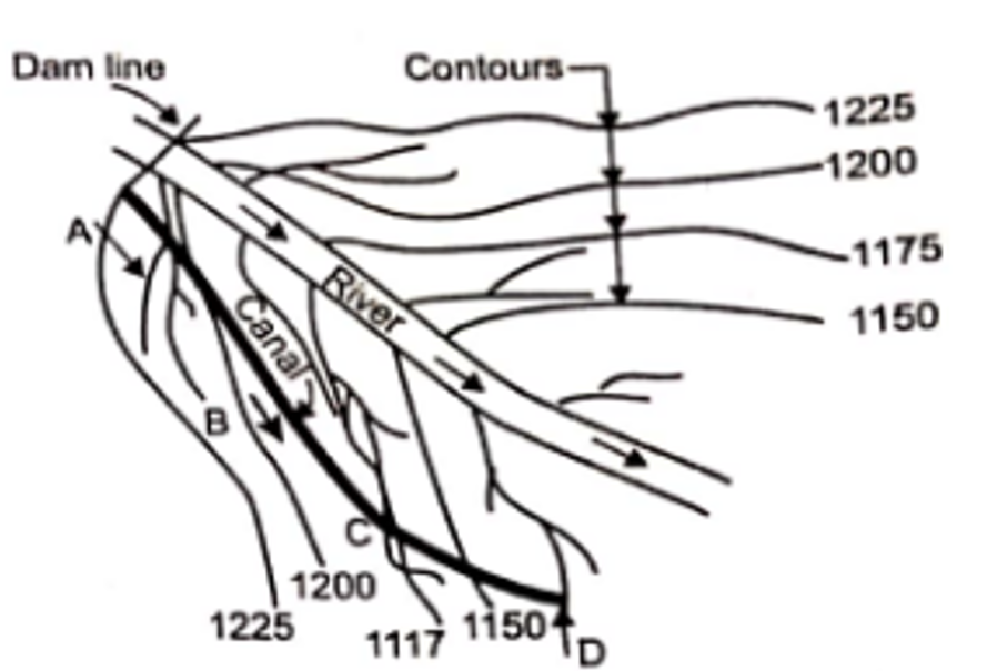
- Economical than ridge canal.
- Suitable for contour farming.
- Irrigation only one side so serves small area.
3. Side slope canal:

- Canal aligned perpendicular to contour line.
- Doesn’t require cross drainage structure.
Consideration during alignment of canal:
- Alignment should not pass through valuable land, religious site, village etc.
- Alignment should be short as possible.
- Alignment should be straight as possible.
- Alignment should not involve heavy cutting or filling.
- Alignment should done such way minimum number of cross drainage are required.
- Alignment should cross natural drainage.
- Ridge or watershed is preferred so both side can be irrigated.
4.5 Canal seepage and evaporation and other losses:
1. Evaporation:
- Evaporation losses are about 2% to 3 % of total losses.
- Depeds upon meteorological factors like temperature, wind velocity and humidity.
2. Seepage:
a. Percolation:
- In percolation there exits a continuous zone of saturation from the canal to the water table.
- A direct flow is established between canal and ground water reservoir.
b. Absorption:
- In absorption a small saturated zone exits round the canal section.
- A small zone above water table is also saturated by capillary action.
- An unsaturated zone exits between these two saturated zone.
Factors on which seepage loss depends:
- Types of seepage (Percolation loss is more)
- Soil permeability (More permeable soil more seepage loss)
- Seepage through silted canal is more than from a new canal.
- More amount of silt less loss.
- More velocity less loss.
- Cross-section and wetted perimeter.
4.6 Tractive force approach in canal:
- The movement of sediment at bed is caused by a force exerted on its grains by the flowing water. The force is known as tractive force.
- Consider a grain of weight ‘w’ represented by dotted circle on the side slope and hollow circle on a horizontal bed of channel as shown in figure below.
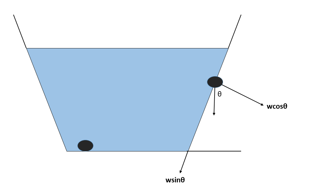
Critical shear stress at horizontal loads = τL = τC = wtanΦ
Critical shear stress at slopping surface = τS
Angle of repose of soil = Φ
We know,
(τS)2 + (wsinθ)2 = (wcosθ*tan Φ)2
or, (τS)2 + ((τL * sinθ)/ tan Φ)2 = ((τL* cosθ*tan Φ)/ tan Φ)2
or, (τS)2 + ((τL * sinθ)/ tan Φ)2 = (τL* cosθ)2
or, (τS / τL)2 = cos2θ – sin2θ / tan2 Φ
or, (τS / τL)2 = (1- sin2 θ – sin2 θ / tan2 Φ)
or, (τS / τL)2 = (1- sin2 θ (1+1/tan2 Φ)
or, (τS / τL)2 = (1- sin2 θ (1+cot2 Φ)
or, (τS / τL)2 = (1- sin2 θ *cosec2 Φ)
or, (τS / τL)2 = (1- sin2 θ/sin2 Φ)
∴ τS / τL = (1- sin2 θ/sin2 Φ)1/2
Above equation is the required expression.
4.7 Silt theories:
Kennedy’s silt theory:
- According to Kennedy’s “regime channel” are those channels in which neither silting nor scouring takes place.
- This condition is not possible in natural channel.
- Expression of critical velocity.
Vo = 0.55y0.64
Lacey’s regime theory:
- According to lacey a canal showing no silting and no scouring may not be in regime.
- He defined three regime condition:
1. True regime:
- Discharge is constant.
- Flow is uniform.
- Silt discharge is constant.
- Silt grade i.e. type and size of silt is constant.
- Practically not possible.
2. Initial regime:
- Bed slope of a channel varies.
- Cross- section or wetted perimeter remains unaffected.
3. Final regime:
- All variables such as perimeter, depth, slope etc. are equally free to vary and achieve permanent stability called final regime.
In such a channel:
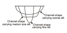
- The coarse the silt, the flatter is the semi-ellipse.
- The finer the silt the more the section attains a semi circle.
Design of canal according to Lacey’s theory:
- Based on final regime.
- The empirical equation is:
V = (2FR/5)1/2 ————-(i)
AF2 = 140V5 —————-(ii)
V = 10.8 R2/3 S1/3————(iii)
Where,
V = Mean velocity of flow in m/s
F = Silt factor = 1.76(Dmm)1/2
Dmm = Average size of particle in mm
A = Cross section area in m2
S = Bed slope
Relation derived from Lacey’s formula:
1. Perimeter discharge relation:
P = 4.75 (Q)1/2
Proof:
From equation (i)
V = (2FR/5)1/2
or, V4 = 4F2R2 / 25
From equation (ii)
AF2 = 140V5
Eliminating F2 from the equation and substituting R = A/P
V4 = (4*140V5 *R2)/25A
or, V4 = (560V5 *A2)/(25*A*P2) [∴R = A/P]
or, P2 = 22.4Q
∴ P = 4.75 (Q)1/2
2. Regime slope equation:
S = F5/3/(3340*Q1/6)
Proof:
From equation (iii)
V = 10.8 R2/3 S1/3
Cubing on both side
V3 = 1259.712 R2 S
We have,
R = 5 V2 / 2F
or, R2 = 25 V4 /4F2
Now,
V3 = 1259.712S [(25 V4)/4F2]
or, S = F2 / 78732V ———(iv)
Again,
V = (QF2/140)1/6
Now, equation (iv) becomes
S = F2/[7873.2*(QF2/140)1/6]
On simplifying we get
∴ S = F5/3/(3340*Q1/6)
3. Hydraulic Radius:
R = 5V2/2F
Proof:
From equation (i)
V = (2FR/5)1/2
Squaring on both side
V2 = 2FR/#
∴ R = 5V2/2F
Difference between Lacey’s theory and Kennedy’s theory:
| Lacey’s theory | Kennedy’s theory |
| i. Relation between V and R. | i. Relation between V and y. |
| ii. Silt factor is taken. | ii. Critical velocity is taken. |
| iii. Equation for bed slope is taken. | iii. Equation for bed slope is not taken. |
| iv. Does not involve trial and error. | iv. Trial and error method is taken. |
4.8 Advantage and economics of canal lining:
Advantage of canal lining:
- Seepage control. (Treated with less permeable material)
- Prevention of water logging.
- Increase channel capacity.(Less resistance to flow of water)
- Reduction in maintenance cost.
- Elimination of flood risk.
Types of lining:
1. Hard surface lining:
- Cement concrete lining
- Brick lining
- Boulder lining
2. Earth type lining:
- Soil cement lining
- Compacted earth lining
Economics of canal lining:
a. Annual benefits (AB):
Suppose,
m cumec water is saved by lining the canal.
The cost of irrigation water to farmers = R1 rupees per cumec
Let, annual cost of maintaing existing unlined canal = R2 rupees
Suppose,
P% of maintenance cost is saved due to lining of canal.
Thus,
Annual benefits (AB) = mR1 + PR2
b. Annual cost (AC):
Let,
The capita expenditure required for lining = C rupees
Life period of lining = Y years
Using principle of time value of money, the total cost is converted into annual cost (AC) by multiplying it with capital recovery factor (CRF).
AC = Cost * CRF
Where,
CRF = (i*i)N *i / (1 + i)N – 1
Thus,
Annual cost (AC) = Cost * [(i*i)N *i / (1 + i)N – 1]
Hence,
Benefit cost ratio = AB/AC
For economic justification benefit cost should be greater than 1.
References:
- WECS (1998), Design Guidelines for Surface Irrigation in Terai and Hills of Nepal, (Vol. I and II)
- Michael, A.M.(2011). Irrigation theory and practice
- FAO(1977). Guidelines for Predicting Crop Water Requirements. FAO Irrigation and Drainage Paper No. 24.