
1.1 Head work:
- Head work is constructed at the head of canal to divert the river water towards canal.
Types:
1. Storage head work:
- Headwork capable of seasonal regulation of water.
- Dam is constructed to use during time of deficit.
2. Diversion headwork:
- Headwork can regulate water daily, weekly or monthly.
- Consist of weir or barrage.
Types of diversion headwork:
- Temporary diversion headwork
- Permanent diversion headwork
Function of diversion headwork:
- Helps to raise the water level in upstream side.
- Regulates supply of water into canal.
- Creates pond on upstream to store water.
- Control silt entry into canal.
- Reduce fluctuation in the level of supply in river.
Components of headwork:
1. Weir or barrage:
Weir:
- Solid construction across the river to raise water level.
- Less costly.
- After long time it becomes ineffective due to silt deposition.
Barrage:
- Water is collected in upstream mainly due to large gates constructed over concrete weir.
- More costly.
- Quantity of water can be controlled.
2. Under sluice:
- To control the entry of silt into canal.
- To ensure easy diversion of water even during low flow.
3. Divide wall:
- To separate the under sluice portion from the weir portion.
- Increase effectiveness of under sluice portion.
4. Fish ladder:
- Provide just by side of divide wall for free movement of fishes.
5. Canal head regulator:
- Regulates the supply of water entering the canal.
- Prevent river flooding from entering into the canal.
Difference between silt excluder and silt extractor:
| Silt excluder | Silt extractor |
| i. Located in the under sluice section of the river. | i. Located on the canal at some distance away from the head regulator. |
| ii. Structure is heavy. | ii. Structure is light. |
| iii. Good approach condition is difficult to achieve. | iii. Good approach condition is easy to achieve. |
| iv. Tunnel are quite large. | iv. Tunnel are small. |
1.2 Condition and cause of failure of hydraulic structure in alluvial formation:
1. Failure by piping or undermining:
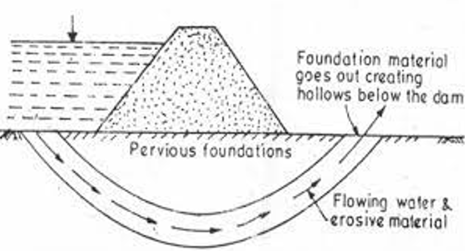
- When the seepage water retains sufficient residual force at the emerging downstream end of work it may lift up the soil particle. This leads to increased porosity of soil by progressive removal of soil from beneath the foundation. The structure may ultimately subside into the hollow so formed resulting in the failure of the structure.
2. Failure by direct uplift:
- The water seeping below the structure exerts an uplift on the floor of structure. If the force is not counterbalanced by the weight of the concrete or masonry floor, the structure will fail by a rapture of a part of the floor.
1.3 Bligh’s, Lanes and Khosla’s seepage theory:
Bligh’s seepage theory:

Assumption:
- Loss of head is proportional to the length of creep.
- Hydraulic gradient is constant throughout seepage path.
Let, there be level difference between upstream and downstream.
Creep length (L) = d1 + d1 + L1 + d2 + d2 + L2 + d3 + d3
or, L = (L1 + L2) + 2 (d1 + d2 + d3)
or, L = b + 2 (d1 + d2 + d3)
Hydraulic gradient = HL/ [b + 2 (d1 + d2 + d3)] = HL / L
Lane’s weighted creep theory:

- Improvement of Bligh’s theory.
Lane creep length (L) = d1 + d1 + L1 / 3+ d2 + d2 + L2 /3+ d3 + d3
or, L = (L1 + L2)/3 + 2 (d1 + d2 + d3)
or, L = b/3 + 2 (d1 + d2 + d3)
Hydraulic gradient = HL/ [b/3 + 2 (d1 + d2 + d3)] = HL / L
Khosla’s theory:

- Khosla’s theory states that “seeping water doesn’t creep along the bottom contour of hydraulic structure.”
- Water moves along a set of stream lines.
- Seepage is governed by Laplacian equation:
d2 Φ / dx2 + d2 Φ / dz2 = 0
1.4 Cross drainage structure, condition for their application and design:
- Cross drainage is constructed at crossing of canal and natural drain to dispose drainage water without interrupting the continuous canal supplies.
Types:
1. Passing canal over drainage:
- Aqueduct
- Syphon aqueduct
2. Passing canal below drainage:
- Super passage
- Syphon
3. Passing drain through the canal:
- Level crossing
- Inlet and outlet
1.5 Canal Escape:
- Canal escape is a side channel constructed to remove surplus water from an irrigated channel into natural drain.
Types:
1. Weir type:
- Reduce level is equal to full supply level.
2. Regulator type:
- Better control.
- Used for completely emptying the canal.

1.6 Canal drops:
- Canal drop is used to bring down the canal bed line.
Types of fall:
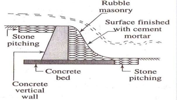
1. Ogee fall:
- Used in old days.
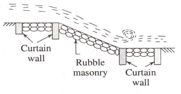
2. Rapid fall:
- Provide with long sloping floor.
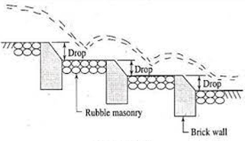
3. Steeped fall:
- Provided long stepped floor.
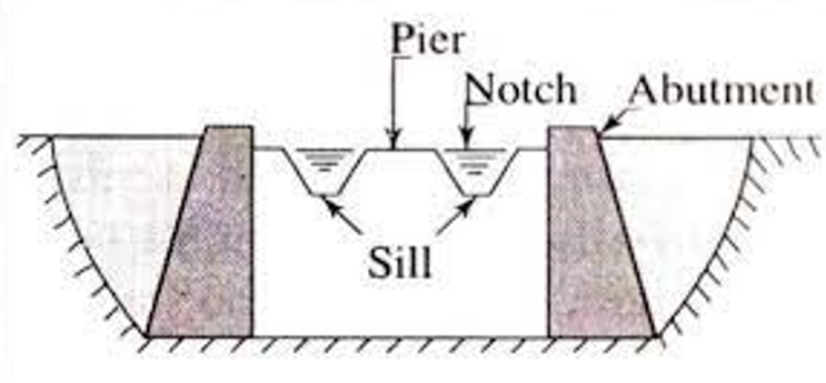
4. Trapezoidal notch fall:
- Consist of number of trapezoidal notch.
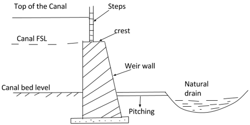
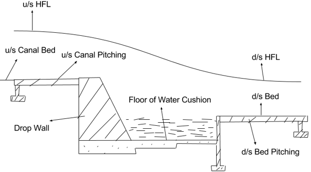
5. Vertical drop fall:
- Crest wall created to create vertical drop.
1.7 Function of head and cross regulator:
Head regulator:
Function:
- Structure provided at head of canal to control flow of water entering into different branch canal.
- Control or regulate supply of water entering different branch canal.
- To control silt entry.
- Used as meter to measure discharge.
Cross regulator:
Function:
- Used to raise the water level.
- Effectively control the entire canal irrigation system.
- Raise the water level if parent channel is low.
1.8 Canal Outlet:
- Canal outlet is a small structure built at the head of water course to connect minor or distributary.
Requirement of good outlet (module):
- Should be simple which can be constructed easily.
- Should work effectively with small working head.
- Should be cheap.
- Any interference by local people should be made difficult and easily detectable.
- Should be strong and durable.
Types:
1. Non – modular outlet:
- Minimum head loss.
- Easy to construct.
- Cheap.
- Unequal distribution of water.
2. Semi – modular outlet:
- Equal distribution of water.
- Easy to construct.
- Expensive.
3. Rigid modular outlet:
- Equal distribution of water.
- Costly.
- Requires skilled manpower.
References:
- WECS (1998), Design Guidelines for Surface Irrigation in Terai and Hills of Nepal, (Vol. I and II)
- Michael, A.M.(2011). Irrigation theory and practice
- FAO(1977). Guidelines for Predicting Crop Water Requirements. FAO Irrigation and Drainage Paper No. 24.