

Introduction
Triangulation and Trilateration is a horizontal control survey whose purpose is to determine the position of a number of control points or stations precisely. The basic framework of the control points are the triangles both in the triangulation and trilateration.
Triangulation
It is the method of providing control points by measuring all the angles of a triangle and length of a line called Base line. The length of all other sides of the triangle are computed from the measured angles and the length of base line.
Trilateration:
It is the method of establishing the control stations for providing horizontal control in which the length of all the sides of the triangle is measured. The distances are measured with Electronic Distance Measuring Instrument (EDM) with an accuracy of 1 ppm to 5 ppm.
But these days due to advent of EDM’s Trilateration is more in use as compared to triangulation.
Data required to start Triangulation
a. Azimuth of a line
b. Coordinates of a point
c. Length of base line

Objective of Triangulation and Trilateration:
- To establish control for plane and geodetic surveys of large areas.
- To assist in the determination of the size and shape of the earth by making observations of latitude and departure.
- To establish accurate control for photogrammetric surveys of large areas.
- To determine accurate locations of points in engineering works such as:
- Fixing centre lines and length of bridge axis of long bridges over large rivers.
- Fixing centre lines, terminal points for long tunnels.
- Detection of crustal movements.
Classification of Triangulation/ Types of Triangulation System:
Layout of Triangles:
1. Simple Triangles:
This is usually employed in long and narrow surveys of low precision such as for a valley or a narrow body of water.

There is only one route in this system to compute the length of unknown sides while the other systems provides at least two routes. So there is no extra check.
2. Double Chain Triangles:
This is used for covering the larger width of 2 belt of land.

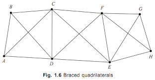
3. Braced Quadrilaterals:
These are better than the chain of simple triangles. There is more than one route for computing the lengths of a side. Hence, the accuracy is increased.
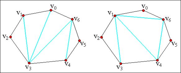
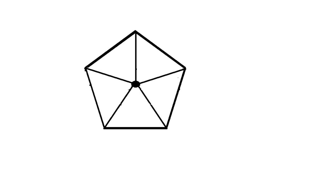
4. Polygons:
In all of the above cases, we directly measure the length of a side and bearing at every 100 station and compare it with the computed value.
Qualities of good figure
- The figure should be such that the computations can be done through two independent routes.
- The figure should be such that at least one (if both better) routes should be well conditioned.
- All the lines in a figure should be of comparable lengths.
- The figures should be such that least work may secure maximum progress.
Field works in Triangulation
- Reconnaissance
- Fraction of signals and towers
- Measurement of base line
- Measurement of horizontal angles.
- Measurement of vertical angles.
- Astronomical observations to determine the azimuth of the lines
Office works in Triangulation
- Adjustment of observed angles
- Computation of lengths and sides
- Computation of the coordinates of the stations
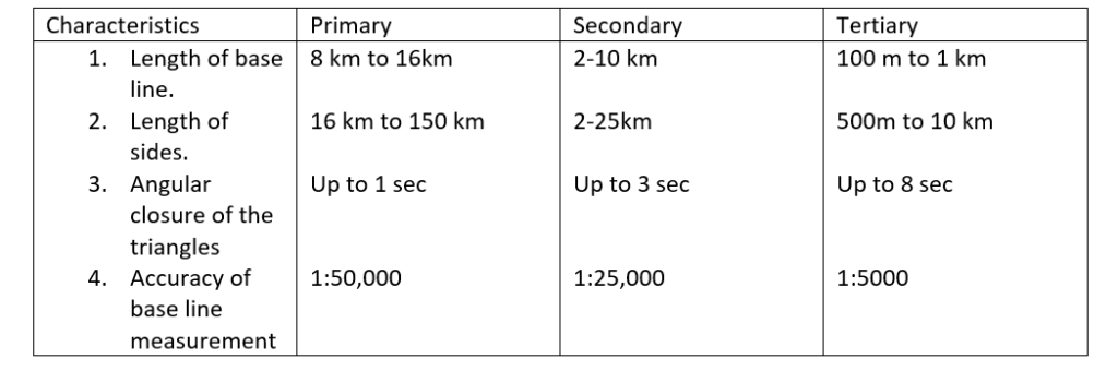
Accuracy of Triangulation
The primary measure of the precision of triangulation is the average triangulation error i.e. the average deviations of the sum of the measured angle in the triangle form 1800 after correction for curvature.
In a small triangle whose sides are of the order of 2 km, the curvature of earth may be considered negligible and three measured angles should sum to 1800. In practice there will be a difference of a number of seconds known as Triangulation Error.
In a large triangles, error arises from the fact that, though the angles are measured in the horizontal plane, the curvature of earth causes these planes non parallel with each other. The three angles should now sum to more than 1800. The increment is called Spherical Excess.
Σ (Measured Angles) – ( 1800 + E ) = ɛ
Where,
E = Spherical excess
ɛ = Triangulation error
The spherical excess is calculated from E= A/ ( R2 sinθ )
Where,
A= Area of the triangulation
R= Mean radius of the earth
Application of Triangulation / Trilateration
- The establishment of accurately located control points for survey of large areas.
- The accurate location of engineering works such as:
- Center line, terminals points and shafts for long tunnels.
- Center line and abutments for bridges of long span.
- Complex highway interchange
- The accurate establishing of control points in connection with the Aerial survey.
- Measurement of deformation of structures such as dams.
- The study of gradual and secular movements in the earth’s crust in areas subject to seismic or tectonic activities.
- To test and construct defense and scientific facilities on high precision, engineering projects.
Advantage and Disadvantage of Trilateration
Advantage:
- Trilateration is a practical and highly accurate means of rapid control extension when properly executed, it is superior to both triangulation and traverse.
- Basic trilateration is less expensive than classical triangulation and under most conditions it is more accurate.
- In trilateration, it is not required to measure lines which all signals simultaneously in position as with triangulation.
Disadvantage:
- Trilateration has a smaller number of internal checks compared to triangulation.
- Higher order trilateration requires sampling of metrological condition to have high precision in distance measurement
- Reflector arrays have to be fixed at the station for the use of EDM. In triangulation, light signals are sufficient
Comparison of Triangulation and Trilateration:
- In triangulation, length of at least one line called the Base line is measured and rest of angles of the triangle is measured. In trilateration, lengths of all the sides of the triangles are measured directly and no angular measurements are made.
- In triangulation, lengths of all the remaining sides of the chain of triangles and hence the position of all the remaining stations are computed in terms of measured angles and measured lengths of the base line. In trilateration, lengths are measured directly.
- In triangulation, the distance are computed from the angular observations. In trilateration, angles are calculated from linear observations.
- The number of redundancies in triangulation is significantly higher than in trilateration i.e. triangulation provides more number of conditions equations or degree of freedom than in trilateration.
Example:
In trilateration: One redundancies
In triangulation: Six redundancies
Electronic Distance Measurement (EDM):
Presents days EDM’s use either infrared ( light waves) or microwaves (radio waves). The microwave system require a transmitter and receiver at both ends of the measured line, where ass the infrared systems require a transmitter at one end and reflecting prism at the other end. Microwave systems are after used in hydrographic surveying and hence have a usual upper measuring range limit of 50 km.
Infrared EDM’s come in long range ( 10 – 20 km), medium range ( 3 to 10 km) and short range ( 0.5 to 3 km)
GPS system
A network of satellite that continuously transmit coded information for locating a point an earth by measuring the distance from the satellites receiver.
GPS satellite
A group of U.S Department of Defense satellite constantly circling the earth and transmitting very low power radio signals.
Fee
No subscription fees or set up changes to use ordinary GPS.
Segment of GPS
1. Space Segments ( Satellites)
- 24 satellite ( 21 active plus 3 spares)
- Satellites about 12000 miles above the earth surface
- At least 6 of them can be received at any time
- At a speed of 7000 miles an hour and 2 times a day
2. Control Segment ( Control Station)
- Controls the GPS satellites( by tracking them and the providing them with corrected orbital and time information)
- Five control stations ( 4 unmanned monitoring station and 1 master control station)
3. User Segments
- Consists a person using GPS and GPS receiver.
Points worth Remembering
- Needs to receive at least 3 satellites for 2D.
- With 4 satellites it gives elevation too.
- Horizontal position is accurate between 7 and 15m if :
- The satellite are far enough and not in the same direction.
- Not in the same line.
- There is a lot of satellite received. But elevation is never reliable ± 35m
- The antenna has to be upright if GPS has an external antenna.
- GPS is more accurate after some minutes than just after it begins to give accuracy value.
Working Principle:
- 3 satellites for 2D position(x,y)
- 4 or more satellite for 3D(x,y,z)
- GPS receivers compares the time transmitted by satellite with its time
- Time difference tells GPS receiver how far away the satellite is
I.e. Distance = Velocity of radio wave * Travel line
References: 1. A text book of surveying and levelling, R. Agor , Khanna publication