
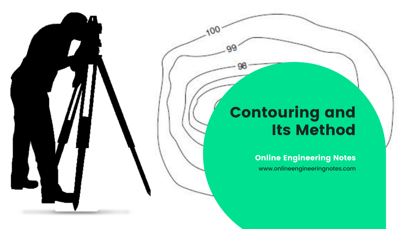
Basic definition in Contouring:
- A line joining points of equal elevations is called a contour line.
- It helps to visualize the relief of ground in two dimensional plane or map.
- The method of plotting contours in a plan or map is called conturing. A contour line marked by a heavier line weight to distinguish it from intermediate contour lines is called index contour line.
An index contour line shows the elevation of nearby contour line.
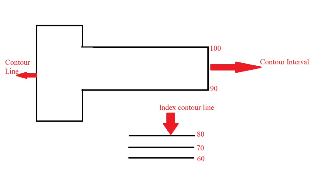
Contour interval:
The difference in elevation between successive contour lines on a given map is fixed. This vertical distance between any two contour lines in a map is called the Contour Interval ( CI) of the map. The choice of a suitable contour interval in a map depends upon four principle considerations.
- Nature of the ground:
The contour interval depends upon the nature of the ground. For flat ground, a small contour interval is choosen, whereas for undulating ground, higher contour interval is chosen.
- Scale of map:
The contour interval normally varies inversely to the scale of the map i.e. if the scale of map is large, the contour interval is considered to be small and vice versa.
- Accuracy:
Accuracy needed in survey work also decides the contours interval. Surveying for detailed design work or for earthwork calculations need high accuracy so small contour interval is used. But in case of location surveys where the desired accuracy is less, higher contour interval should be used.
- Time and cost:
If the contour interval is small greater time and cost is required in survey and map plotting. So, if the available time and cost is limited larger contour interval is used.
Horizontal Equivalent:
The horizontal distance between two points on two consecutive contour lines for a given slope is called the horizontal equivalent.
Characteristics of Contour:
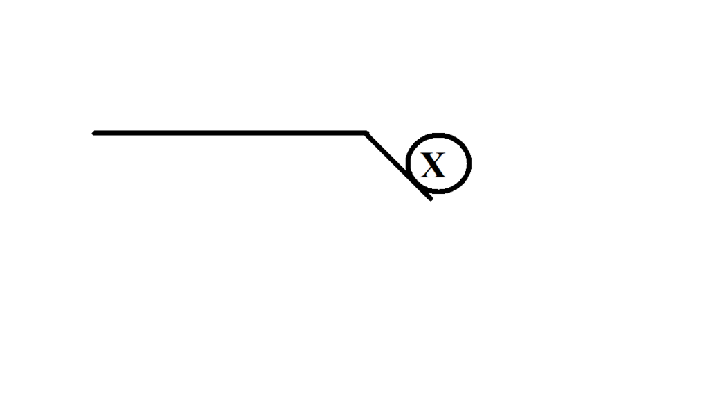
a. Two contour lines donot cross each other except in the case of overhanging cliff.
b. Contour overlap or unit in a single line in case of vertical cliff.

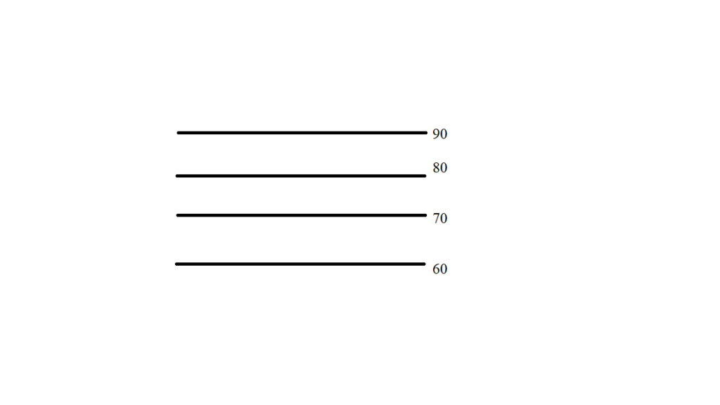
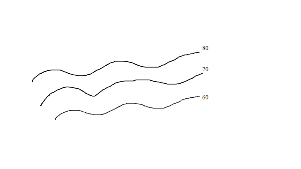
c. If the contour lines are parallel and distance apart then it shows that the ground is gentle slope.
d. If the contour line are spaced closer and non-uniform then it shows steep and undulated ground.
e. A contour line must close upon itself through not necessarily within the limits of the map.

f. A single contour line cannot split into two contour line.
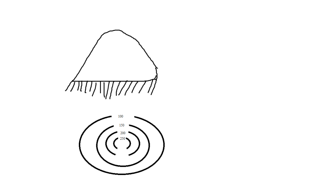
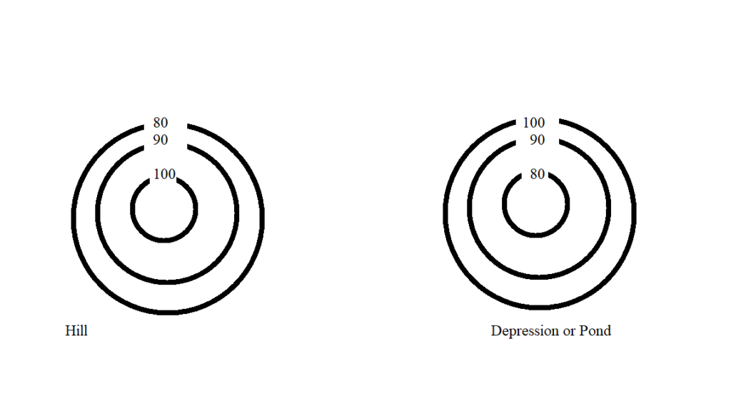
g. A closed contour line with one or more higher one inside represents a hill; similarly contour line with lower value inside indicates a depression or pond.
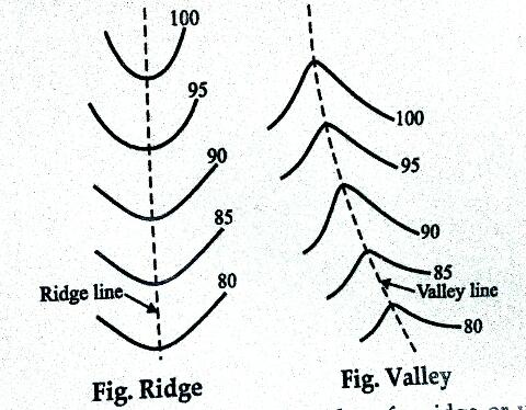
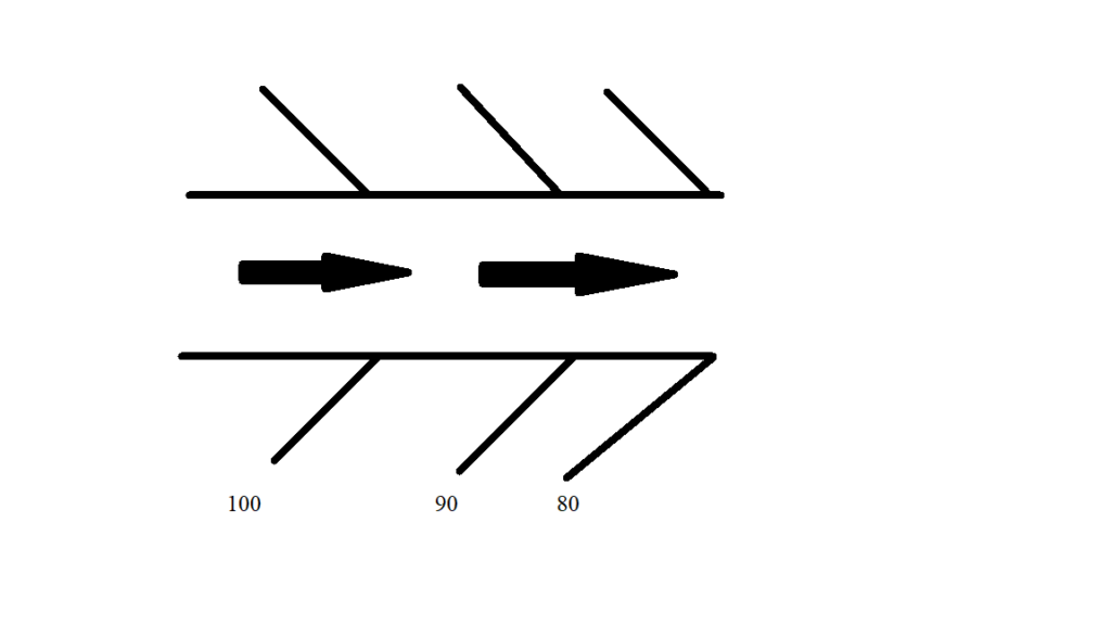
h. Contour cross a water shead or ridge line at right angles. Thery form curves of U-shape around it with concave side of the curve towards the higher ground. Contour cross a valley line at right angles. They form sharp curves of V-shape across it with convex side of the curve towards the higher ground.
i. Contours donot cross a river or stream.
j. Contour donot have sharp-turings.
Methods of contouring
The method of establishing/ plotting contours is a plan or map is known as conturing. In general the field methods of conturing may be divided into two classes:
a. Direct method and
b. Indirect method
a. Direct method:
Indirect method, the contour to be plotted is acutually traced on the ground. Only the required points are surveyed then plotted. In this method work has mainly two folds.
- Vertical control:
If 100m RL is to be plotted then first staff is placed on BM and then HI is to be found out, then staff point is searched on ground for the required RL of 100m as :
RL= HI – Staff reading
( Staff reading = HI – RL)
When the staff(ground) point is located by required staff reading it is pegged and number of such types of points are joined to form the contour line.
- Horizontal control:
When the required points on the ground are located then such points should be suitably controlled by the control points or lines. In small area chain survey may be used but in large area traverse may be required.
b. Indirect method:
- Square method:
This method is suitable if the are is small and ground is not very much undulating. The area to be surveyed is divided into is number of squares. The size of squares may vary from 5-20m depending upon the contour and contour interval. The RL of each square corner are determined then required contour line is interpolated.
- Cross section method:
In this method, cross-section’s are run transverse to the center line of a road, railway or canal etc. This method is most suitable for railway route survey. Spacing of the cross section depends upon the terrain of the land.
- Tacheometric method:
This method is suitable for hilly terrain. In this method contour point is located by stadia hair reading and the RL of the points are found. Instruments is places at fixed positions and reading is taken in a radial line at different angles and then RL of different points are found out.
Interpolation of contours:
It is the process of spacing the contours between the plotted points. This method is based on the assumption that the slope of ground between two points is uniform.
- Bye-eye estimation:
This method is extremely rough and is used for small scale work only. The position contour points between the guide points are located by estimation.
- By arthmetic calculation:
This method is accurate but time consuming. Contour between the guide points are located by arithmetic calculation.
- Graphical method:
In graphical method a piece of tracing paper in which several lines are drawn parallel to each other is used to located to contours.
Uses of contours map:
- Nature of ground can be understood by studying contour map. So, planning can be performed without visiting site.
- A suitable site for economical alignment can be selected for any engineering project.
- Capacity of a reservoir or the area of a catachment can be approximately computed.
- The inter visibility between two points can be determined.
- A suitable route for a given gradient can be marked on the map.
- A section of the ground surface can be drawn in any direction.
- Quality of earthwork can be computed.
- Measurement and calculation of drainage area can be done.
References: 1. A text book of surveying and levelling, R. Agor , Khanna publication